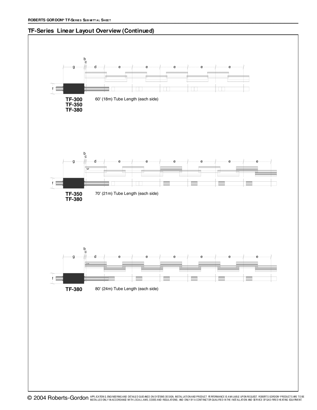
TF-Series specifications
The Roberts Gordon TF-Series is a renowned line of infrared radiant heaters that exemplify efficiency and effectiveness in heating solutions. Designed for commercial and industrial applications, the TF-Series is engineered to provide comfortable heating in large spaces while minimizing energy consumption. One of its standout features is the use of high-intensity infrared heating technology, which directly warms people and objects in a space rather than just the air. This results in faster heat delivery and consistent warmth, contributing to enhanced comfort for occupants.The TF-Series model incorporates several advanced technologies that set it apart in the market. Among its key characteristics is the advanced reflector system that maximizes heat distribution. These reflectors are engineered to direct infrared rays downwards, ensuring even heating across the floor space. The design also reduces heat loss, making the system highly efficient in energy usage. This makes the TF-Series ideal for environments where energy conservation is a priority, such as warehouses, factories, and outdoor settings.
Another notable feature is the flexibility of installation options. The TF-Series heaters can be mounted in various configurations, including overhead suspension or wall mounting, allowing for adaptability to the specific layout of any facility. This flexibility ensures that users can position the heaters optimally to achieve maximum coverage and efficiency.
Moreover, the TF-Series is built with durability in mind. The units are constructed from high-quality materials that can withstand the rigors of commercial environments. This resilience guarantees a long lifespan, which is vital for businesses looking to minimize maintenance costs over time.
In addition to functional features, the TF-Series excels in user-friendly operation. Many models come equipped with integrated controls that allow for easy temperature adjustments and programmability, facilitating a sophisticated approach to energy management. This capability not only enhances comfort but can also lead to significant reductions in operational costs.
Overall, the Roberts Gordon TF-Series embodies a blend of innovative technologies, practical design, and robust construction. Its advanced heating solutions cater to a wide range of commercial and industrial applications, making it a preferred choice for those seeking efficient and effective heating solutions in larger spaces. The combination of direct infrared heating, effective reflector systems, adaptability in installation, and user-friendly controls distinguishes the TF-Series as a market leader in heating technology.

