4. Operation
1.Turn on your source components.
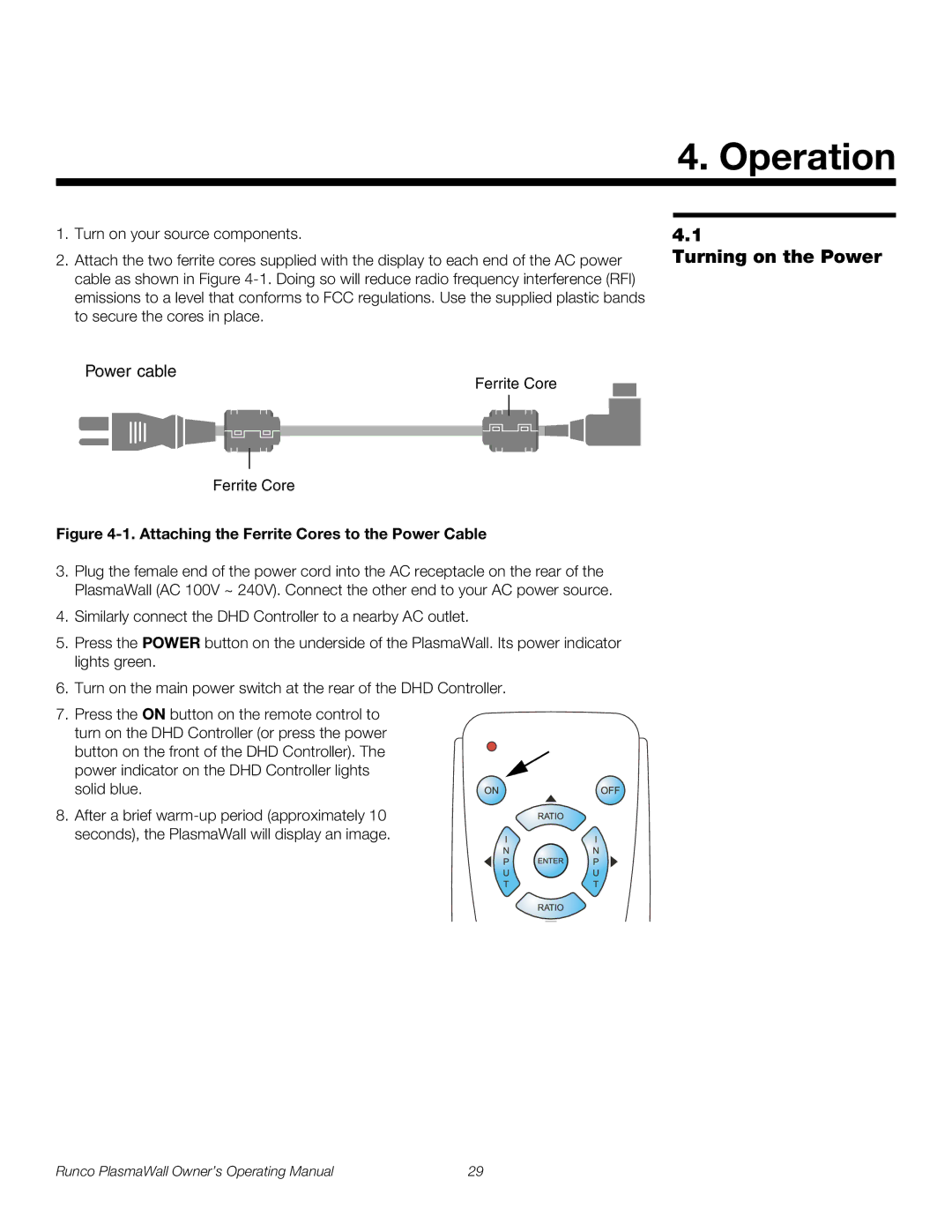
2.Attach the two ferrite cores supplied with the display to each end of the AC power cable as shown in Figure
Power cable
Ferrite Core
Ferrite Core
Figure 4-1. Attaching the Ferrite Cores to the Power Cable
3.Plug the female end of the power cord into the AC receptacle on the rear of the PlasmaWall (AC 100V ~ 240V). Connect the other end to your AC power source.
4.Similarly connect the DHD Controller to a nearby AC outlet.
5.Press the POWER button on the underside of the PlasmaWall. Its power indicator lights green.
6.Turn on the main power switch at the rear of the DHD Controller.
7.Press the ON button on the remote control to turn on the DHD Controller (or press the power
button on the front of the DHD Controller). The power indicator on the DHD Controller lights solid blue.
8. After a brief
4.1
Turning on the Power
Runco PlasmaWall Owner’s Operating Manual | 29 |