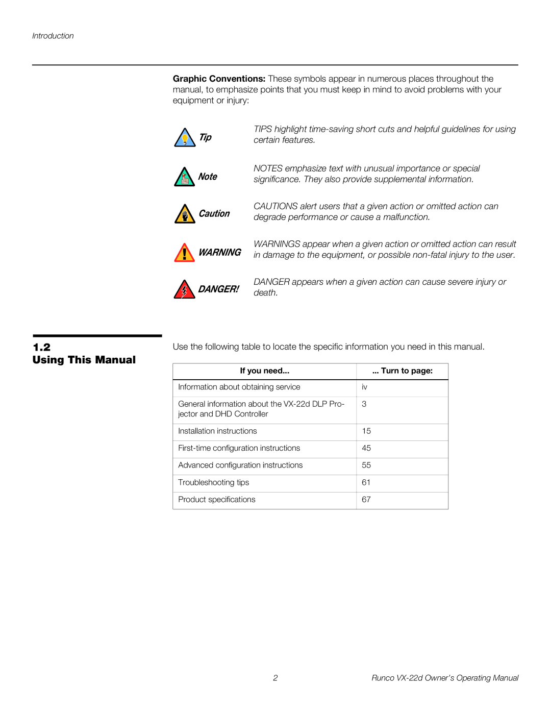
OW N E R ’S OP E R A T I N G MA N U A L
1080p, 3-chip Digital Light ProcessingTM Projector and DHD Controller
VX-22d
Page
WHAT IS NOT COVERED UNDER THE TERMS OF THIS LIMITED WARRANTY
TWO YEAR LIMITED WARRANTY
WHAT IS COVERED UNDER THE TERMS OF THIS LIMITED WARRANTY
For Projectors, Video Processors and Controllers
CONTACT A RUNCO AUTHORIZED SERVICE CENTER TO OBTAIN SERVICE
EFFECTIVE WARRANTY DATE
IMPORTANT - WARRANTY REGISTRATION
COPYRIGHT AND TRADEMARKS
Toll Free 800 23-RUNCO
RUNCO INTERNATIONAL, INC Attn Customer Service Department
2900 Faber Street Union City, CA Ph 510 Fax 510
ADDITIONAL INFORMATION
Safety Precautions
Safety Precautions
Table of Contents
TWO YEAR LIMITED WARRANTY
Installation
Installing the Optional CineWide/AutoScope Lens Motor
Filter Replacement
Maintenance and Troubleshooting
Lamp Replacement
Specifications
Table of Contents
Runco VX-22d Owner’s Operating Manual
List of Figures
Runco VX-22d Owner’s Operating Manual
List of Figures
Runco VX-22d Owner’s Operating Manual
About This Manual
A carriage return must be used after each command or string
1. Introduction
Target Audience
DANGER appears when a given action can cause severe injury or
1.2 Using This Manual
certain features
DANGER
format screen
1.3 Description, Features and Benefits
Key Features and Benefits
Optional Accessories
Figure 2-1. VX-22d Front/Bottom/Side View 1. INTAKE VENT
2. Controls and Functions
2.1 VX-22d at a Glance
2. LENS OPENING 3. RUNCO LOGO
2. RUN LED
2.2 VX-22d Rear Panel
Figure 2-2. VX-22d Rear Panel 1. LAMP COVER
3. LEFT BUTTON
11. SERVICE PORT
8. SOFT POWER BUTTON
10. POWER INPUT 100 to 240 VAC Connect the VX-22d to power here
9. PATTERN BUTTON
2. IR SENSOR
2.3 DHD Controller Front Panel
Figure 2-3. DHD Controller Front Panel 1. RUNCO ICON
3. VACUUM FLUORESCENT DISPLAY VFD
6. DOWN BUTTON
10. ISSUE LED
14. SOFT POWER BUTTON
7. RIGHT BUTTON
When an external remote control or infrared receiver is connected
3. MAIN POWER SWITCH
5. SERVICE ONLY For future use 6. WIRED REMOTE
Note to the wired IR input, the IR sensor on the front of the DHD
9. HDMI I 1 / HDMI II 2 Digital
For best results, do not run your DVD player in progressive mode
8. 12-VOLT 750 mA TRIGGER OUTPUTS
10. HD3 INPUT
Controls and Functions
2.5 VX-22d Remote Control
Figure 2-5. VX-22d Remote Control
2. ON / OFF
5. Picture Adjustment Buttons BRT Brightness
1. LIGHT
3. Source Selection Buttons VID
ISF DAY
6. Memory Preset Buttons CUST1
ISF NIGHT
CUST2
Notes on Batteries Notes on Remote Control Operation
3. Installation
3.1 Remote Control
Installation should be performed by a qualified custom video
3.2 Quick Setup
Table 3-1. Installation Overview
installation specialist
Installation Type
3.3 Installation Considerations
Table 3-2. Projector Installation Options
Ambient Light
Table 3-3. VX-22d Lens Options and Throw Ratios
Figure 3-1. Estimating Throw Distance
Figure 3-2. Projector Placement
Ceiling Installation
Floor Installation
Vertical and Horizontal
lens or projector is used in this example
Figure 3-4. Horizontal Lens Shift EXAMPLE ONLY
Installation
100% Width Lens Shift 1.0 x W 50% Width Lens Shift 0.5 x W
Figure 3-5. Folded Optics
Table 3-4. VX-22d Vertical and Horizontal Lens Shift Limits
Folded Optics
3.4 Installing the Primary Projection Lens
Other Considerations
3. Remove the Lens Cavity Front Cover 4. Remove the Rear Lens Cap
Remove Projector Front
3.5 Installing the Optional CineWide/AutoScope Lens Motor
unexpected disconnection or lens damage
Feet
lens motor housing with those on the
Install AutoScope Lens
Motor
Installation
Figure 3-6. VX-22d With Ceiling Mount Extension Brackets
Install Ceiling Mount
Extension Brackets
3.6 Mounting the VX-22d
projector. Install the mount kit according to the instructions
Adjusting the Projection
Floor Mounting Upright
You CANNOT connect a signal source with DVI output directly to
Connector Panel Access
Connecting the DHD
Figure 3-7. Connecting the VX-22d to the DHD Controller
Use the HDMI inputs whenever possible. This ensures the highest
Connecting Source Components to the DHD Controller
HDMI Connections See Figure
Figure 3-8. HDMI Source Connections
B/Pb
Figure 3-9. Digital DTV RGB or Component Video Connections HD1, HD2
Installation
R/Pr
Runco VX-22d Owner’s Operating Manual
Figure 3-10. Digital DTV RGB or Component Video Connections HD3
Installation
DTV or Progressive Component YPbPr Source
Installation
Analog Computer RGB Connections See Figure
Figure 3-11. Analog RGB Connections
Personal Computer
Figure 3-12. S-Video and Composite Video Connections
S-Video/Composite Video Connections See Figure
DVD Player, VCR Satellite Receiver Laser Disc etc
Installation
Connection
to Automation/ Control System or PC
RS-232 Controller
Figure 3-13. RS-232 Control System Connection
Connecting 12-Volt Trigger Outputs to External Theater Equipment
Figure 3-14. 12-volt Trigger Output Connections
Receiver to the DHD
Connecting an External IR
built-in IR sensor on the DHD Controller is disabled
Controller
Connecting to AC Power
3.8 Turning on the Power
3.9 Adjusting the Picture Orientation
to a 200-240 VAC power source
Primary Lens
Adjustments
3.10
Focus
Figure 3-16. VX-22d Anamorphic Lens Mounting Assembly - Exploded View
3.11 Installing and Adjusting the CineWide Anamorphic Lens
Attach Lens Mounting Assembly to Lens Motor Carriage Plate
It is extremely important that the primary lens is properly
Figure 3-17. Attaching the Anamorphic Lens to the Lens Adapter Ring
ENTER
Adjusting the Horizontal X Lens Position
Configure Lens Motor Trigger Adjust the Anamorphic Lens
There may be some pincushion distortion even after the lens is
Too Low Correct position Too High
Correct Position Wrong Position
Anamorphic Lens Top View
Installation
Runco VX-22d Owner’s Operating Manual
Adjusting the Geometry
Wrong Position
4.1 Using the On-Screen Menus
4. Operation
Input Source
ISF Presets
Service
Aspect Ratio
Input Source
Note resolution
Main Menu
The aspect ratio selection is automatically saved for each input and
Table 4-1. Aspect Ratio Settings
Operation
Table 4-1. Aspect Ratio Settings continued
Picture
When you change a picture quality setting, save the change to a
Figure 4-2. Typical PLUGE Pattern for Adjusting Brightness
yellow
Figure 4-3. Typical Gray Bar Pattern for Adjusting Contrast
gray
cyan
cyan
gray
yellow
green
Input Position
Figure 4-5. Typical Test Pattern for Adjusting Sharpness
and resolution
ISF Presets
Information
You must enter a passcode to access the Calibration menu
Calibration
ISF Day - Input Image Refer to ISF Night - Input Image
Gain/Offset Refer to ISF Night - Display Color, above
ISF Day - Display Color Refer to ISF Night - Display Color
ISF Day - Input Color Refer to ISF Night - Input Color
effect the next time you select that input not immediately
or DHD Controller front panel to enter and exit test pattern mode
Service
You must enter a passcode to access the Service menu
and ISF Day/Night presets page
at all times. Lamps may explode if dropped or mishandled
5. Maintenance and Troubleshooting
5.1 Lamp Replacement
If you inhale the mercury vapor, see a physician immediately
5.2 Filter Replacement
Side Filter Access Panel
Maintenance and Troubleshooting
5.3 Troubleshooting Tips
Table 5-1. Troubleshooting Chart
Runco VX-22d Owner’s Operating Manual
Maintenance and Troubleshooting
Runco VX-22d Owner’s Operating Manual
If you are using a PC to communicate with the DHD Controller
6.1 RS-232 Connection and Port Configuration 6.2
Serial Command Syntax
6. Serial Communications
Table 6-1. Serial Commands
EXIT Enter
Table 6-1. Serial Commands continued
MBR Enter MNR Enter MNR Enter MNR Enter MNR Enter MNR Enter
Serial Communications
Runco VX-22d Owner’s Operating Manual
Table 7-1. VX-22d Specifications
7. Specifications
VX-22d Specifications
Runco VX-22d Owner’s Operating Manual
Table 7-1. VX-22d Specifications continued
Specifications
Specifications
7.2 DHD Controller Specifications
Table 7-2. DHD Controller Specifications
Runco VX-22d Owner’s Operating Manual
3.91 10.08 16.26
7.3 VX-22d Dimensions
Specifications
10.23
Page
SERIAL NUMBER
Runco CL-810 Owner’s Operating Manual
RUMA-000105 rev 03-22-07