CineWide with AutoScope maintains constant image height independent of the aspect ratio, while using the full display resolution of the projector. It accomplishes this by moving the anamorphic lens in front of the primary lens when widescreen material is being viewed. When the viewer transitions back to 16:9 or 4:3 source material, the anamorphic lens moves out of the light path.
To configure the lens motor trigger on the DHD Controller for proper AutoScope operation:
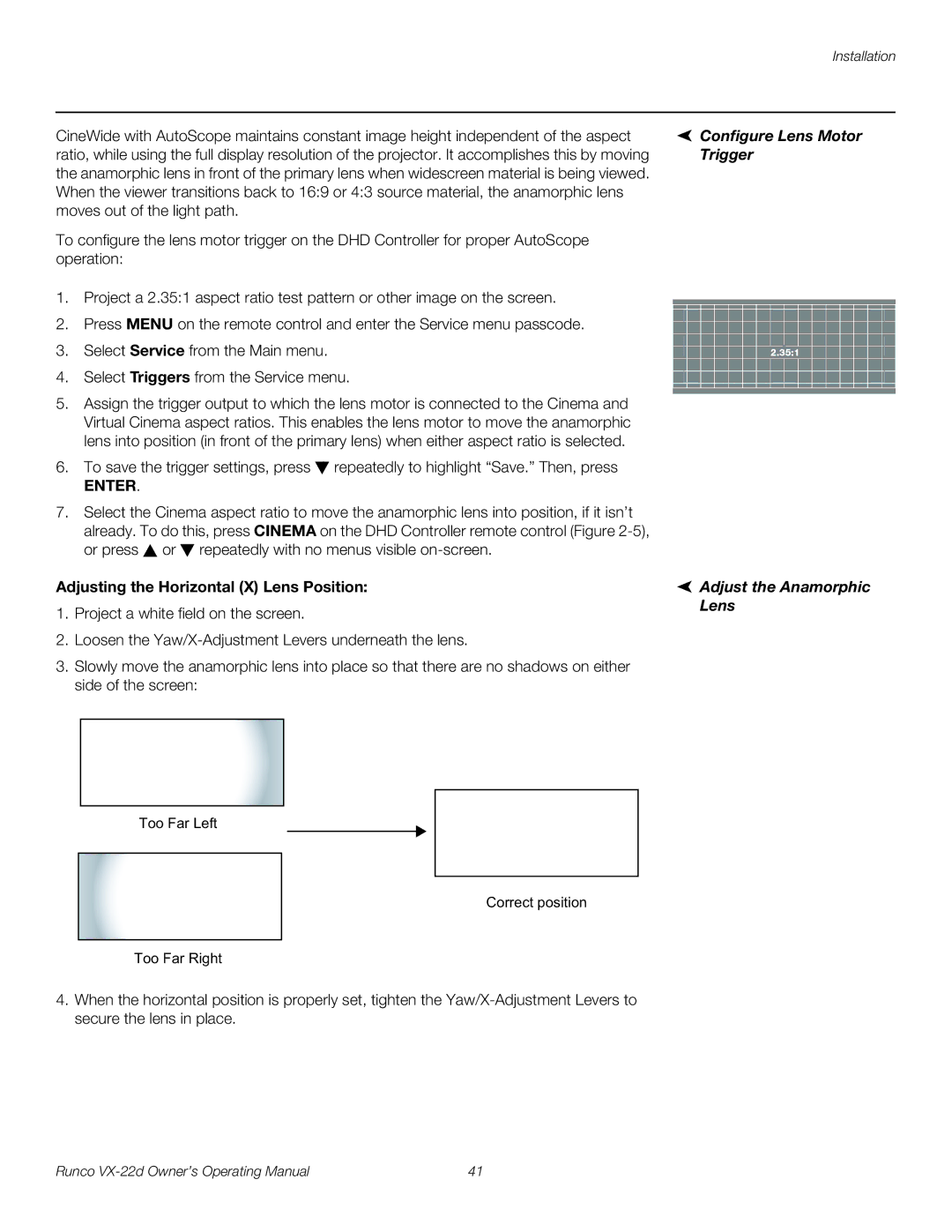
1.Project a 2.35:1 aspect ratio test pattern or other image on the screen.
2.Press MENU on the remote control and enter the Service menu passcode.
3.Select Service from the Main menu.
4.Select Triggers from the Service menu.
5.Assign the trigger output to which the lens motor is connected to the Cinema and Virtual Cinema aspect ratios. This enables the lens motor to move the anamorphic lens into position (in front of the primary lens) when either aspect ratio is selected.
6.To save the trigger settings, press ![]() repeatedly to highlight “Save.” Then, press
repeatedly to highlight “Save.” Then, press
ENTER.
7.Select the Cinema aspect ratio to move the anamorphic lens into position, if it isn’t already. To do this, press CINEMA on the DHD Controller remote control (Figure ![]() or
or ![]() repeatedly with no menus visible
repeatedly with no menus visible
Adjusting the Horizontal (X) Lens Position:
1.Project a white field on the screen.
2.Loosen the
3.Slowly move the anamorphic lens into place so that there are no shadows on either side of the screen:
Too Far Left
Correct position
Too Far Right
4.When the horizontal position is properly set, tighten the
 Configure Lens Motor Trigger
 Adjust the Anamorphic Lens
Runco | 41 |