Operation
Contrast: On your external test pattern source, select a stepped,
Figure 4-3. Typical Gray Bar Pattern for Adjusting Contrast
Select Contrast and press ENTER or SELECT. Adjust the contrast to a point just below which the white rectangle starts to increase in size.
Brightness and contrast controls are interactive. A change to one
Note may require a subtle change to the other in order to achieve the optimum setting.
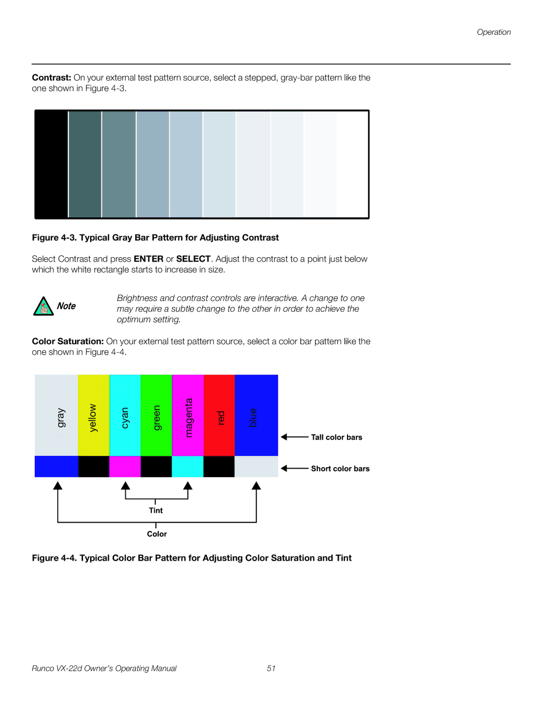
Color Saturation: On your external test pattern source, select a color bar pattern like the one shown in Figure
gray | yellow | cyan | green | magenta | red | blue |
Figure 4-4. Typical Color Bar Pattern for Adjusting Color Saturation and Tint
Runco | 51 |