Serial Communications
Table
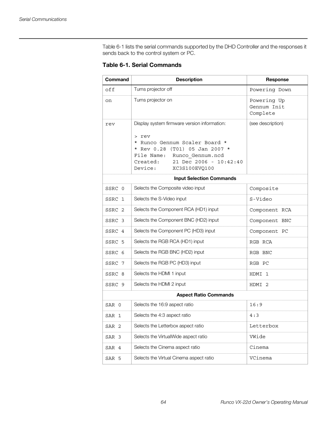
Table 6-1. Serial Commands
Command |
| Description | Response |
|
|
|
|
off | Turns projector off |
| Powering Down |
|
|
|
|
on | Turns projector on |
| Powering Up |
|
|
| Gennum Init |
|
|
| Complete |
|
|
| |
rev | Display system firmware version information: | (see description) | |
| > rev |
|
|
| * Runco Gennum Scaler Board * |
| |
| * Rev 0.28 (T01) 05 Jan 2007 * |
| |
| File Name: | Runco_Gennum.ncd |
|
| Created: | 21 Dec 2006 - 10:42:40 |
|
| Device: | XC3S100EVQ100 |
|
|
|
|
|
Input Selection Commands
SSRC 0 | Selects the Composite video input | Composite |
|
|
|
SSRC 1 | Selects the | |
|
|
|
SSRC 2 | Selects the Component RCA (HD1) input | Component RCA |
|
|
|
SSRC 3 | Selects the Component BNC (HD2) input | Component BNC |
|
|
|
SSRC 4 | Selects the Component PC (HD3) input | Component PC |
|
|
|
SSRC 5 | Selects the RGB RCA (HD1) input | RGB RCA |
|
|
|
SSRC 6 | Selects the RGB BNC (HD2) input | RGB BNC |
|
|
|
SSRC 7 | Selects the RGB PC (HD3) input | RGB PC |
|
|
|
SSRC 8 | Selects the HDMI 1 input | HDMI 1 |
|
|
|
SSRC 9 | Selects the HDMI 2 input | HDMI 2 |
|
|
|
| Aspect Ratio Commands |
|
|
|
|
SAR 0 | Selects the 16:9 aspect ratio | 16:9 |
|
|
|
SAR 1 | Selects the 4:3 aspect ratio | 4:3 |
|
|
|
SAR 2 | Selects the Letterbox aspect ratio | Letterbox |
|
|
|
SAR 3 | Selects the VirtualWide aspect ratio | VWide |
|
|
|
SAR 4 | Selects the Cinema aspect ratio | Cinema |
|
|
|
SAR 5 | Selects the Virtual Cinema aspect ratio | VCinema |
|
|
|
64 | Runco |