FEATURES
Operating Components
The upper portion of the blade projects up through the table and is surrounded by an insert called the throat plate. The height of the blade is set with a handwheel on the front of the cabinet. Detailed instructions are provided in the Operation section of this manual for the basic cuts: cross cuts, miter cuts, bevel cuts, and compound cuts.
The sliding miter table assembly is used for cross cutting operations. The miter fence is easily adjusted to cut wood at an angle by loosening the adjusting clamp, setting the fence to the miter scale, and retightening the clamp. With the miter fence removed, the miter table offers additional support for other operations such as ripping.
The rip fence is used to position work for lengthwise cuts. A scale on the front rail shows the distance between the rip fence and the blade.
It is very important to use the blade guard assembly for all
SWITCH assembly
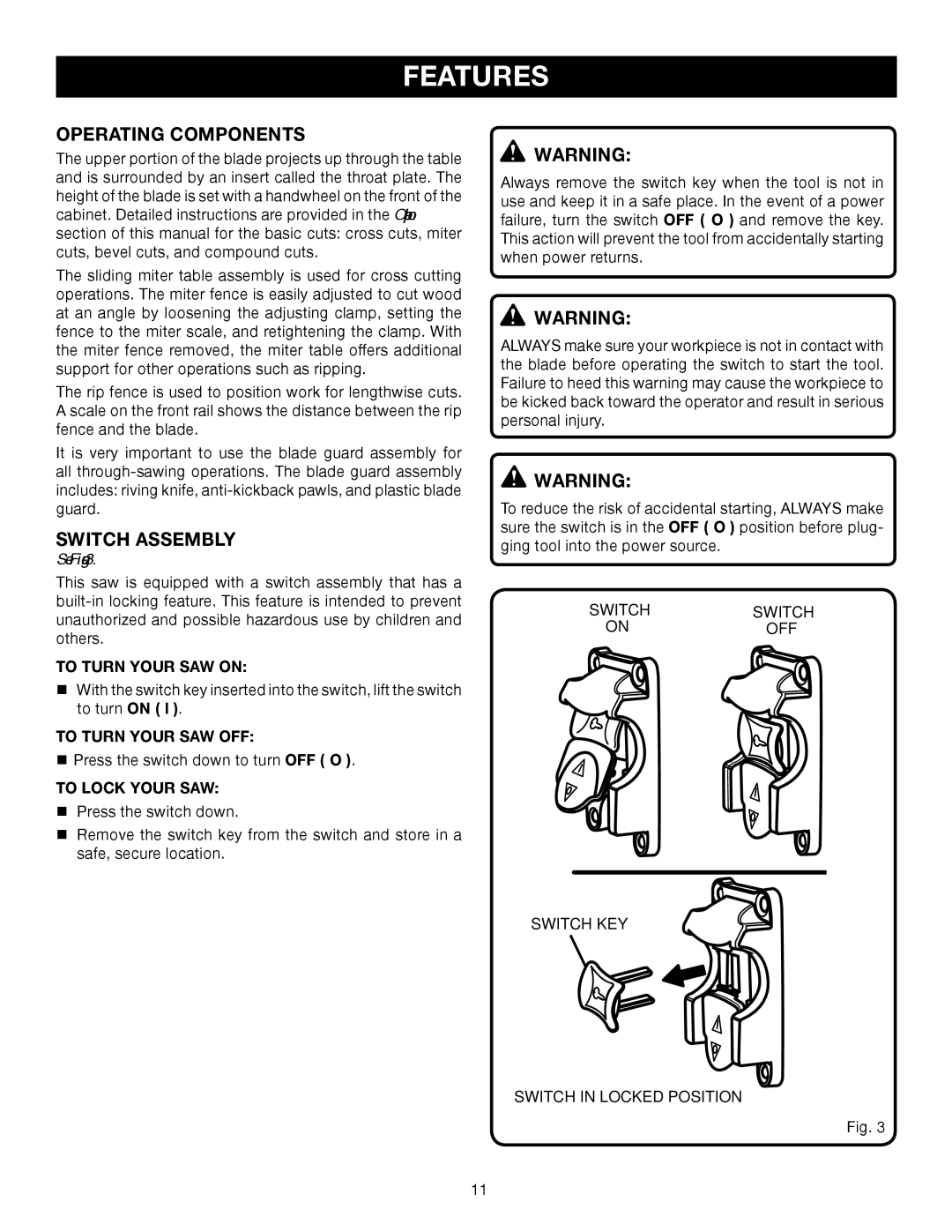
See Figure 3.
This saw is equipped with a switch assembly that has a
TO TURN YOUR SAW ON:
With the switch key inserted into the switch, lift the switch to turn ON ( l ).
TO TURN YOUR SAW OFF:
Press the switch down to turn OFF ( O ).
TO lock your saw:
Press the switch down.
Remove the switch key from the switch and store in a safe, secure location.
![]() WARNING:
WARNING:
Always remove the switch key when the tool is not in use and keep it in a safe place. In the event of a power failure, turn the switch OFF ( O ) and remove the key. This action will prevent the tool from accidentally starting when power returns.
![]() WARNING:
WARNING:
ALWAYS make sure your workpiece is not in contact with the blade before operating the switch to start the tool. Failure to heed this warning may cause the workpiece to be kicked back toward the operator and result in serious personal injury.
![]() Warning:
Warning:
To reduce the risk of accidental starting, Always make sure the switch is in the OFF ( O ) position before plug- ging tool into the power source.
SWITCH | SWITCH |
ON | OFF |
SWITCH KEY
SWITCH IN LOCKED POSITION
Fig. 3
11