operation
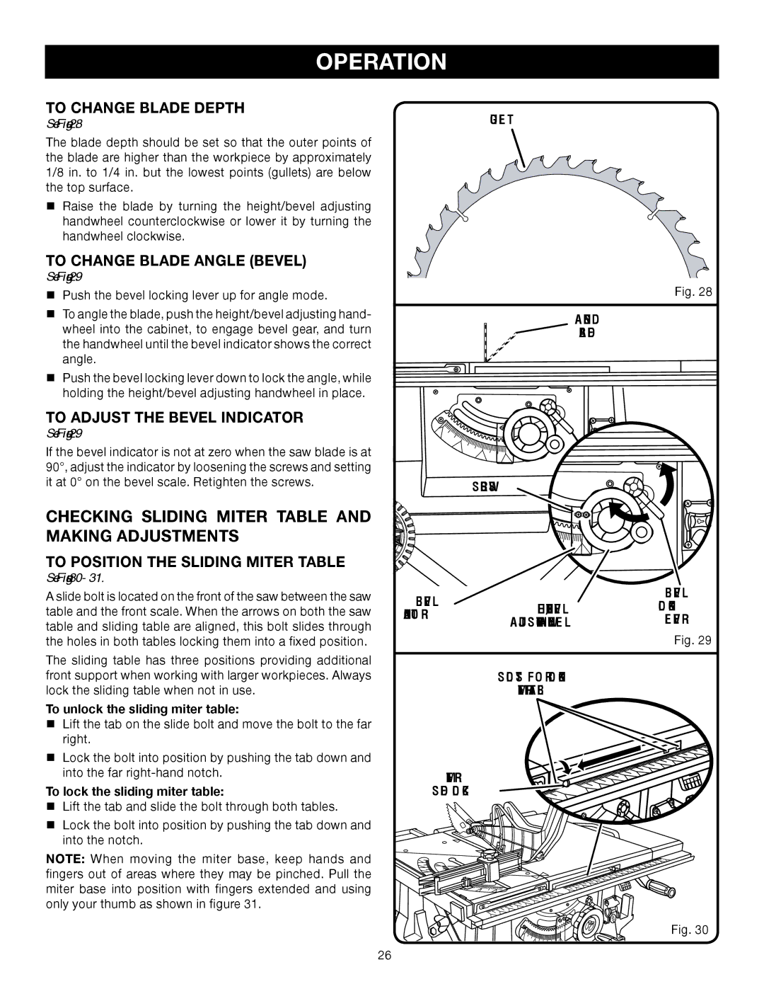
TO CHANGE BLADE DEPTH | gullet |
See Figure 28. |
The blade depth should be set so that the outer points of the blade are higher than the workpiece by approximately 1/8 in. to 1/4 in. but the lowest points (gullets) are below the top surface.
Raise the blade by turning the height/bevel adjusting handwheel counterclockwise or lower it by turning the handwheel clockwise.
TO CHANGE BLADE ANGLE (bevel)
See Figure 29.
Push the bevel locking lever up for angle mode.
To angle the blade, push the height/bevel adjusting hand- wheel into the cabinet, to engage bevel gear, and turn the handwheel until the bevel indicator shows the correct angle.
Push the bevel locking lever down to lock the angle, while holding the height/bevel adjusting handwheel in place.
Fig. 28
angled
blade
To Adjust the Bevel indicator |
|
See Figure 29. |
|
If the bevel indicator is not at zero when the saw blade is at |
|
90°, adjust the indicator by loosening the screws and setting |
|
it at 0° on the bevel scale. Retighten the screws. | screws |
|
CHECKING SLIDING MITER TABLE AND
MAKING ADJUSTMENTS
To position the SLIDING Miter Table
See Figures 30- 31.
A slide bolt is located on the front of the saw between the saw table and the front scale. When the arrows on both the saw table and sliding table are aligned, this bolt slides through the holes in both tables locking them into a fixed position.
The sliding table has three positions providing additional front support when working with larger workpieces. Always lock the sliding table when not in use.
To unlock the sliding miter table:
Lift the tab on the slide bolt and move the bolt to the far right.
Lock the bolt into position by pushing the tab down and into the far
To lock the sliding miter table:
Lift the tab and slide the bolt through both tables.
bevel |
| bevel | |
height/bevel | locking | ||
indicator | |||
adjusting handWHEEL | lever | ||
| |||
|
| Fig. 29 | |
|
|
| |
| SLOTS FOR LOCKING |
| |
| MITER TABLE |
|
Miter
slide lock
Lock the bolt into position by pushing the tab down and ![]()
![]()
![]()
![]()
![]()
![]()
![]()
![]()
![]()
![]() into the notch.
into the notch.![]()
![]()
![]()
![]()
![]()
![]()
![]()
![]()
![]()
![]()
NOTE: When moving the miter base, keep hands and fingers out of areas where they may be pinched. Pull the miter base into position with fingers extended and using only your thumb as shown in figure 31.
Fig. 30
26