DVD Video Recorder
Contents
Functionsreturn
Remote control
Control reference guide
Main unit
Entering titles
Unit’s display
Control reference guide
For your safety
Displays
Disposal of old equipment
Inside of unit
Checking the Accessories
How to replace the Fuse
Check that you have the accessories shown
Dear Customer
Remote control
Remote control signal sensor Switch DVD, TV 15 to DVD
Batteries
Use
Remote control
Television operation
Preparation
Operation Button
Discs
Discs you can use
Discs you can use for recording and play
Play-only discs
Discs that cannot be played
Audio format logos
Types of disc for the type of connected
Discs
Connections with Scart leads
Follow the step-by-step guide below
Pin Scart leads are not supplied
Hint
Connections without Scart leads
Connect the RF Output socket to the TV aerial socket
Connections with S-Video cable
Signals from the Sky Digital STB
Recording RGB Signals
Standby to ensure continuous output of RGB signals
Auto Setup with Q Link Functions
To Set Up this DVD Recorder with a brand-new Q Link TV
Clock. This is called Auto Setup function
Menu for Owner ID setting
Auto Setup without Q Link Functions
To Set Up this DVD Recorder with an existing Q Link TV
Auto Setup with Q Link Functions
To restart Auto Setup
Auto Setup without Q Link Functions
Video Plus+ Codes for Satellite Receivers/Cable TV
Removing Interference
For the United Kingdom
Selecting TV screen type
Use 3, 4 10 to select the TV aspect and press Enter
To return to the previous screen
≥169
Erasing a programme that is being played
When a menu screen appears on the television
Playing discs
Starting play from where you stopped it Resume Function
Fast forward and rewind-SEARCH
Slow-motion play
Frame-by-frame viewing
Selecting an amount of time to skip Time Slip
Skipping
Manual Skip
When using DVD-R
Changing audio
Marking positions directly
Using Display menus to mark positions
Marking places to play again Marker
Using menus to play MP3 discs
Using the tree screen to find a group
Recording television programmes
Stop recording
EXT Link
To perform Direct TV Recording
Playing while you are recording
Simultaneous recording and play
To stop play and recording
Press Direct Navigator
Using the Functions window
Using the Functions window
Checking the recording during recording Time Slip
Watching the television while recording
Using the Functions window
Functions window icons
Timer recording
Using Video Plus+ number to make timer recording
Press Video Plus+ 2 button
Press the numeric buttons 4 to enter the Video Plus+ number
Timer recording
To change the programme
To put the unit on recording standby
To change the timer recording programme
Manual programming
Starting and canceling programmes
To clear a timer recording programme
To put the unit on recording standby Press , Timer
To check programmes
When connected to the other equipment
Recording from a video cassette player
To select the TV system PAL/NTSC
Use 3, 4 10 to select the TV system and press Enter
About Disc Information
Entering titles
Enter Title
Disc Information
Disc Protection
Releasing disc protection
Erase all programmes
Format
To stop finalizing
Finalize Creating DVD-Video
Use 3, 4 10 to select Finalize and press Enter
Using the Direct Navigator
Selecting programmes to play
To clear the programme list
About the programme list
Entering and editing programme titles
Checking programme contents
Erasing programmes
Protecting programmes
Releasing programme protection
Padlock mark appears
Select No in and press Enter Press Return
Erasing parts of a programme
Dividing programmes
To erase another part of the same programme
To change the point to divide
About the Play List Scene screen
Using Play List to edit programmes
Displaying Play List
Using Play List to edit programmes
Creating Play List
To erase a Play List or a Play List Scene during play
Playing Play List
Playing Scenes
Adding Scenes to a Play List
Moving a Scene
To re-edit a Play List Scene
Erasing a Scene from a Play List
Checking Play LIST’s contents
Copying Play List
Erasing a Play List
Titling Play List
Disc menu
Using Display menus
Common procedures
Using Display menus
Play menu
Picture menu
Sound menu
Repeat play
Use 3, 4
Display changes as illustrated
PRG PROGRAMME,-.All,-.OFF
Connecting external equipment
To cancel the Child Lock
Enjoying more powerful sound
Child Lock
Connecting a digital amplifier or system component a
Connecting an analog amplifier or system component B
Connecting external equipments
To enjoy Dolby Pro Logic
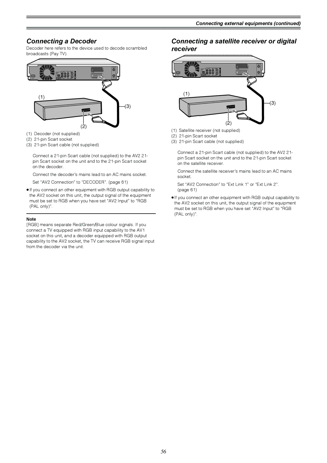
Connecting a Decoder
Connecting a satellite receiver or digital receiver
Connecting a video cassette recorder
Audio/Video cable
Yellow Video White L Red R
Rear panel of this unit
Press Functions
Changing the unit’s settings
≥Switch DVD, TV 15 to DVD
Summary of settings
Tuning
Settings
Changing the unit’s settings
Picture
Sound
Display
Connection
Entering a password Ratings
Digital output
Changing the unit’s settings Auto Clock Setting
Clock Settings
Manual Clock Setting
Channel Settings
Selecting the manual tuning
Handling the Tuning BOX screen
Nicam
Auto-Setup Restart, Download
Changing the Owner ID
Shipping Condition
Status displays
Changing the information displayed
Display examples
Press Status 28 to change the information displayed
Disc handling
Maintenance and Handling
Maintenance
Glossary
Glossary
Link
Title/Chapter DVD-Video
Track
Service Unit status Solutions Number
Recover
Self-diagnosis
No Read
Information
Error displays
Error messages Causes and solutions
Troubleshooting guide
Power
Picture
Sound
Troubleshooting guide
Remote control
Remote control doesn’t work Cannot operate the television
Play
Recording and timer recording
Specifications
Index
16, 17
Disc 10, 20, 26
Dolby Digital 11, 54, 62
Page
Page
F0103Fa0