ED2250S/P
122 F , low
Be sure to use only the supplied adapter
Instructions alert you to
Potential risk of death
Installation environment requirements
Procedures of the ED2250S/P and provides preparation
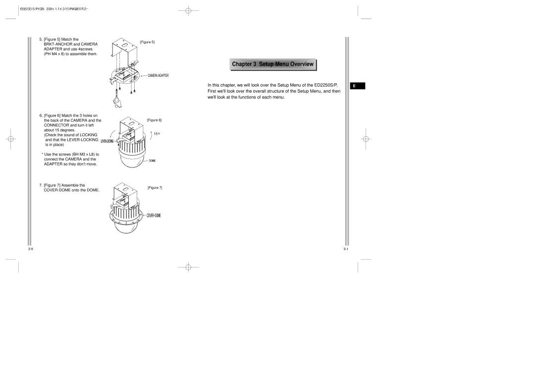
ED2250S/P, part names and functions, and Switch Settings
Explains the installation
Table of contents
Chapter
ED2250S/P Introduction
Cover Body Cover Dome Zoom Lens
Locations of Control
ED2250S/P Adapter Board
Dip Switch setting is same as the following example
RS-422A/RS-485 Full Duplex Organization
Switch Setting
Termination
RS-485 Half Duplex Organization
100
177
Checking Package Contents
ED2250S/P Installation Before Installing
Video Cable
Power Adapter Cable
Preparing the Cables
Cable Connection
Installing ED2250S/P
Installation Precautions
Separately Sold Products for Installation
Built in by the builder of the structure
Installing the Camera
Ceiling Mount Adaptor SADT-100CM
Pole Mount Adaptor SADT-100PM
Chapter
Structure of the Setup Menu
Sync
Camera SET Menu
Camera ID
COLOR/BW
Exit
Video SET Menu
Zoom Speed
Motion DET
If the object were in motion it would be blurry
ALC
Manu
Shutter
Fast
AGC
Slow
Normal
User Set the appropriate value in the RED and Bule graph
Temperature only one time
Preset menu
White BAL
Zoom
POSI/NEGA Video output signal is outputted normal/reverse
Special
Auto Focus
Preset
Auto Mode
Alarm SET
Other SET
Product specifications
CAM Reset
Select SET Level and set the Level of Mask Area
Memo
Benutzerhandbuch
Schließen Sie nicht mehrere Kameras an einen Adapter an
Warnung
Achtung
Gekennzeichneten
Erläutert die
Vor Inbetriebnahme
Anhang a Technische Daten der Speed-Dome Kamera
Normzulassungen
Weitere Prog
Inhaltsverzeichnis
Kapitel 1 Überblick über die ED2250S/P
Einführung in die ED2250S/P
Rückseite
Steuerungselemente
Benutzen Sie die Ziffern 5 bis 8 PINs von SW501, um das
Verwenden Sie PIN 3 und 4 von SW501
91-10
RS-422A/RS-485 Vollduplex-Betriebsart
Schaltereinstellung
Einstellung der RS-422A/RS-485 Abschlüsse
RS-485 Halbduplex-Betriebsart
100
177
Vor der Installation
Überprüfung des Verpackungsinhalt
ED2250S/PHaltewinkel
Video-Kabel
Vorbereitung der Kabel
Kabelanschlüsse
Netzanschlusskabel
Deckenhalterung SBR-100DCM
Installation der ED2250S/P
Sicherheitshinweise für die Installation
Separat erhältliches Zubehör für die Installation
Eingebaut vom Hersteller
Installation der Kamera
Deckenhalterung SADT-100CM
Masthalterung SADT-100PM
Bild7 Bringen Sie die
PH M4X8 fest
Überprüfen Sie am
Geräusch, ob das
Aufbau des Setup Menüs
…bedeutet, es gibt Untermenüs
Kamera Prog Menü
Kamera ID
Farbe S/W
Ausgang
Video PROG-Menü
Zoom Gesch
Aktivitaet
Die links, rechts, oben, unten Tasten benutzen
GLK
AUTOX6 AUTOX8
Lang
Norm
Schn
Weissabgl
Auto Fokus
Spezial
Drücken Sie Enter, um in das nächsthöhere Menü zu gelangen
Position Prog
Video Prog
Schwellzeit
Gesch
Start Prog
Richtung
Endlos
Alarm Prog
Einstellung DER Zeit FÜR DEN Home Zurück
Weitere Prog
Home Zurück
Privat Zone
KAM Reset
Technische Daten
Abwärts-Taste
Memo
Manuel d’instruction
Ne branchez jamais plus d’une camera sur un seul adaptateur
Précautions de sécurité
Avertissement
Mise en garde
Homologation des normes
Avant l’utilisation
ED2250S/P
Table des matières
Chapitre 1 ED2250S/P vue d’ensemble
Arrière
Connexion d’adaptateur
Connexion d’adaptateur
Dip Switch setting est même comme l’exemple suivant
Organisation de Plein Duplex RS-422A/RS-485
Arrangement de commutateur
Arrangement de RS-422A/RS-485 d’une terminaison
Terminaison
100
177
Vis Corps de couverturea
Vérification de contenu de paquet
Câble vidéo
Préparation des câbles
Connexion de câble
Câble d’adaptateur électrique
Support DE Fixation AU MUR SADT-100WM
Précautions à observer lors de l’installation
Des dispositifs de montage vendus séparément
Support DE Fixation AU Plafond SBR-100DCM
Installation de la Camera
Support DE Fixation AU Plafond SADT-100CM
Bride DE Montage SUR Poteau SADT-100PM
DôME DôME-COUVERTURE
Chapitre3 Vue d’ensemble de m enu d’installation
Contenu de menu d’installation
’AF de la caméra peut survenir
COULEUR/N&B
Signifie qu’il y a sub-menus
COULEUR/N&B
Sortie
Prog Video
Vite Zoom
DET Mouve
Gauche, Droite
Cjour
Pressez
En bas Keys
Vite
CAG
Lent
LEN
3000K Lampe d’halogène 2000 K
BAL Blancs
10000 K Ciel bleu 9000K Pluvieux 8000 K 7000K Nuageux 6000K
5000K Ensoleillé
Utilisez les clefs Gauche, droite, haut, bas
Il est le même que la fonction de du menu de Prog Camera
VIT Cycle
Prog Position
Prog Video
Balayage
Mode Auto
Prog Alarme
POS Origine
Autre Prog
RET Origine
Zone Privee
RAZ CAM
Spécification du produit
Memo
Manual del usuario
Medidas de seguridad
Advertencia
Precaución
Antes de Instalar el equipo
Capítulo 3 Menú de Ajustes
Aprobación de estándares
Estructura del menú de ajustes
Auto Foco Configuración Conmutadores Zoom Salida
Localización de controles Posterior
Ajuste de la terminación RS-422/RS-485
Capítulo 1 Características del ED2250S/P
Introducción del ED2250S/P
Localización de controles
Cubierta
Cubierta externa Lente Zoom
Conexiones del adaptador
Use PIN 3 y 4 del SW501
Selector SW501
Conexión RS-422A/RS485 en Full Duplex
Configuración Conmutadores
Terminación
Conexión RS-422A/RS-485 en Half Duplex
Dirección de receptor
177
ED2250S/P Anclaje en U
Antes de la instalación
Chequeo del contenido de la caja
Consumo 18 W Voltaje 24 VCA, 1,5 a
Cable coaxial
Preparación del cable
Conexión del cableado
Cable de alimentación
Instalación de la cámara ED2250S/P
Medidas de precaución para la instalación
Productos para la instalación que se venden por separado
Anclaje en U
Instalación de la cámara
Adaptador DE Montaje EN Techo SADT-100CM
Adaptador DE Montaje EN Poste SADT-100PM
Figura Embellecedor
Estructura del menú de ajustes
Posición
COLOR/ByN
Cámara ID
…Significa que hay submenús
VEL Zoom
DET Movi
Salida
Automática
BLC Submenú del menú ALC/MANU
Obturador
100 a 1/10K de un segundo
Orden
Dulc
Rápi
CAG Control automático de ganancia
BAL Blanco
Unoaf
Especial
Auto Foco
POSI-NEGA La señal de salida de vídeo es normal/inverso
… Significa que hay submenús
Prog Posición
Barrido
Ciclo Tiempo
Auto Modo
Prog Prioridad Alarma
Alarma Prog
Prog SAL Alarma
Prog Ronda Alarma
POS DE Orig
Altra Prog
Vuelta Orig
Zona Privada
Tecla Abajo
Aparece el mensaje ? cuando usted seleccionaRESET CÁM
Modo de Configuración de
Especificaciones de producto
Memo
ED2250S/P
Attenzione
Avvertenza
Illustra le
Spiega le procedure
Prima dell’uso
Riconoscimento degli standard
Indice
Introduzione al modello ED2250S/P
Retro
Collocazione dei comandi
Utilizzare i PIN 3 e 4 di SW501
Relay esterno
Impostazioni Preliminari
Sottostante
Divisione Terminazione
Impostazioni DI Selezione
Impostazioni di terminazione RS-422A/RS-485
RS-422A/RS-485 in duplex
Identificativo ricevitore
177
Prima dell’installazione
Controllo del contenuto della scatola
Viti
Cavo video
Preparazione dei cavi
Connessione del cavo
Cavo dell’adattatore
Installazione della telecamera ED2250S/P
Accessori per l’installazione venduti separatamente
Precauzioni da adottare
Intende
Installazione della telecamera
Adattatore PER IL Montaggio a Soffitto SADT-100WM
Adattatore PER IL Montaggio SU Palo SADT-100PM
Figura 7 Assemblare il COPRI-CALOTTA sulla
Calotta
Struttura del menù di Setu
Indica la presenza di sottomenù
Menu Prog Camera ID Camera
Menu Prog Video
Activity DET
Uscita
Usare i pulsanti
BLC sottomenù del menù ALC/MANU
Fisso
Lento
Veloc
AUTOX6
BIL Bianco
PIP Immagine nell’immagine quando è attivo lo zoom digitale
Speciale
Scansione
Posizione iniziale, Preset 1 Preimpostata 1 ALLARMI1
Preset 2 ALLARMI2, Preset 3 ALLARMI3, Preset
Prog Posizione
Modo Auto
Prog Allarmi
POS Iniziale
RIT POS Iniz
Zona Privacy
Tempo Impostato PER IL Ritorno Alla Pagina Principale
Giù
Specifiche di prodotto
ED2250S/P
Completare le impostazioni relative alla zona riservata
Memo