1CH Blu-ray Home Cinema System
English
Safety Information
Safety Warnings
Class 1 Laser Product
Precautions
Handling and Storing Discs
Holding discs
Disc Storage
Licence
Contents
Using the Search and Skip Functions
Power On/Off Sound
Software Upgrade
Using the Tools button
Getting Started
Icons that will be used in manual
DVD-RAM
Discs that cannot be played
HD DVD Disc
Blu-ray Disc
Region code
Disc Types
Disc Format
Music File Support
Supported File Formats
Video File Support
AC3
AAA size ASC Microphone
Accessories
Supported devices
Front Panel
Description
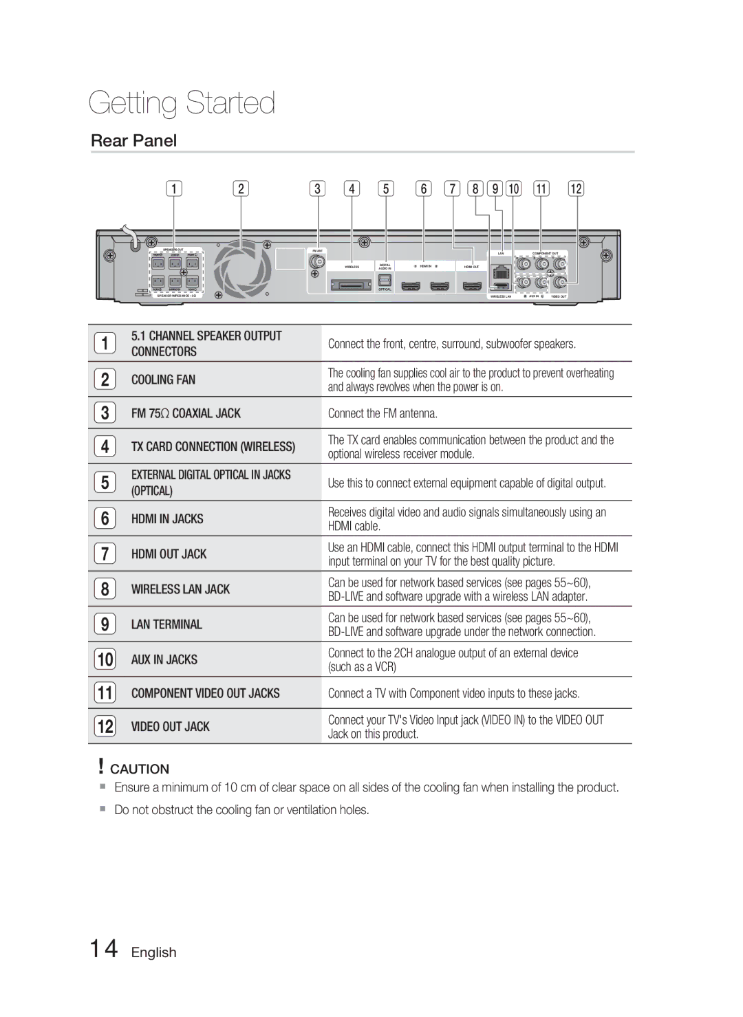
Rear Panel
Used to set a preset radio
Adjust the volume
Information when playing
Press this to link to various Internet@TV services
Installing batteries in the Remote Control
TV Brand Code List
Setting the Remote Control
If the TV turns off, the setting is complete
Connecting the Speakers
Connections
HT-C5500
Speaker Components
Speaker Components Assembled Speakers
HT-C5550
Case of HT-C5500
Installing the Speakers on the Tallboy Stand
Connecting The Speakers
Surround Speaker L
Connecting the Optional Wireless Receiver Module
Front Speaker R Subwoofer
TX card
Connections
Hdmi
Hdmi OUT Connecting to a TV with an Hdmi Cable Best Quality
Connecting External Devices/your TV via Hdmi
Hdmi OUT
Hdmi Auto Detection Function
Method 2 Composite Video Good Quality
Connecting the Video Out to your TV
Method 1 Component Video Better Quality
Yellow
Connecting Audio from External Components
Optical Connecting an External Digital Component
AUX Connecting an External Analogue Component
Broadband modem With integrated router
Connecting to the Network
Broadband Service
Connect the FM antenna supplied to the FM 75Ω Coaxial Jack
Connecting the FM Antenna
FM Antenna supplied
This product does not receive AM broadcasts
Press the Enter button to select Start button
Setup
Before Starting Initial Settings
Musical Auto Calibration screen will be displayed
Setting the Menu
BD Wise Samsung Products only
Resolution
TV Aspect
Display
Blu-ray Disc playback Output Hdmi / connected
Resolution according to the output mode
Setup
DVD playback Output Hdmi / connected
Hdmi Format
Progressive Mode
Still Mode
Movie Frame 24 Fs
Level
Speaker Setting
Audio
Distance
Hdmi Audio
Musical Auto Calibration Setting
Musical Auto Calibration
Musical Auto Calibration
Bitstream
Digital Output
Digital Output Selection
Optical
AV Sync
Initial Settings
Dynamic Range Control
Internet@TV Screen Size
DivXR Deactivation
Clock
DivXR Registration
Set time-related functions
Setting Up a Wired Connecton Auto
Network Settings
Wired Network
Setting Up a Wired Connecton Manual
Wireless Network
Setting Up the Wireless Network Connection PBC WPS
Setting Up the Wireless Network Connection Manual
Network Test
BD-Live Internet Connection
Network Status
Language
Parental Rating
Change Password
Power On/Off Sound
Background
Support
Software Upgrade
Contact Samsung
Playback
Using the Disc Menu
Basic Functions
Disc Structure
Searching for a Desired Scene
Using the Title Menu
Using the Popup Menu
Playing the Title List
Repeat the Title or Chapter
Slow Motion Play
Step Motion Play
Repeat the Section
Selecting the Audio Language
Using the Tools button
Moving to a Desired Scene Directly
Selecting the Subtitle Language
Changing the Camera Angle
Selecting the Picture Setting
Setting the Bonusview
Caption Function
Pause button Pauses playback
Buttons on the Remote Control used for Music Playback
Listening to Music
Stop button Stops a track
Playlist
Playing an Audio CD CD-DA/MP3
Repeat an Audio CD CD-DA/MP3
Audio CD CD-DA/MP3 Screen Elements
Sound Mode
SFESound Field Effect Mode
DSPDigital Signal Processor Function
Playing a Jpeg Disc
Dolby Pro Logic II Mode
Using the Tools button
Playing back a Picture
Playing back a USB Storage
Press the buttons to select the desired Videos
Using buttons on the Remote Control
Setting Mono/Stereo
Presetting Stations
Using buttons on the product
Getting Started with Internet@TV
Network Services
Using Internet@TV
Internet@TV at a Glance
Using the Keypad
For example, here is how to search an address in Google Maps
System Setup
Settings
Account Login
Internet@TV ID
Samsung AppS
Service Manager
Internet@TV Services Available
Properties
Network Services
Software Upgrade Notification
Using the AllShare Function
Menu Bar
Application Program at a Glance
During video playback, play time will not display
Troubleshooting
Other information
Then press the Power button
Using the Reset function will erase all stored settings
To the default values
Feature is not available at the moment
PC Share Manager, but
BD-LIVE service
An error occurs BD-LIVE service
Cannot see the files Displayed
Specifications
HT-C5500
HT-C5550
` CIS
Correct disposal of batteries in this product
Руководство пользователя
Pyccкий
Информация по технике безопасности
Предупреждения для безопасного использования
Лазерный Продукт Класса
Меры предосторожности
Хранение и использование дисков
Как следует держать диск
Хранение дисков
Содержание
Экон. энергии
Общее
Фон
Передний дисплей
WMA
Начало работы
Используемые значки
Логотипы воспроизводимых дисков
Совместимость дисков Blu-ray
Невоспроизводимые диски
Типы и характеристики дисков
Региональный код
Типы дисков
Формат диска
Поддержка музыкальных файлов
Поддерживаемые форматы файлов
Поддержка видеофайлов
Принадлежности
Примечания по соединению USB
Поддерживаемые устройства
Музыка
Передняя панель
Описание
Задняя панель
Знакомство с пультом дистанционного управления
Пульт дистанционного управления
Настройка пульта дистанционного управления
Нажмите кнопку POWER, чтобы включить телевизор
Перечень марок телевизоров и соответствующих им кодов
Установка батарей в пульт дистанционного управления
Подключения
Подключение громкоговорителей
Винт 5X15 4 ШТ
Компоненты громкоговорителей
Громкоговорители в собранном виде
Винт 4X20
Для HT-C5500
Установка громкоговорителей на высокую подставку
Подключение громкоговорителей
Боковой Громкоговоритель Л
Подключение дополнительного модуля беспроводного приемника
Центральный громкоговоритель Фронтальный
Плата TX
Примечание
Проигрыватель DVD
Подключение внешних устройств/телевизора через Hdmi
Спутниковая приставка
Функция автоматического определения Hdmi
Подключение видеовыхода к телевизору
Способ 1. Компонентное видео Лучшее Качество
Способ 2. Композитное видео Хорошее Качество
1080p, 1080i или 720p. Фактическое разрешение составляет
Подключение внешних аудиоустройств
Optical подключение внешнего цифрового устройства
AUX подключение внешнего аналогового устройства
Телеприставка Красный
Модем широкополосного вещания
Или
Вещания Служба Широкополосного
Со встроенным маршрутизатором
FM-антенна входит в комплект поставки
Подключение FM-антенны
Нажмите кнопку Ввод и выберите Начать
Настройка
Подготовка к использованию Начальная настройка
Изменений, нажмите кнопку Стоп на Главное меню
Settings Начальная настройка для внесения
Настройка меню
Чтобы повторно отобразить экран Initial
Разрешение
Формат ТВ-экрана
BD Wise только устройства Samsung
Дисплей
Разрешение, соответствующее режиму вывода
Прогрессивная развертка
Формат Hdmi
Видеокадр24Fs
Стабилизация изображения
Расстояние
Настройка громкогов
Уровень
Тест-тон
Настройка автокалибровки музыки
Автокалибровка музыки
Автокалибровка музыки
Return Примечание
ИКМ
Цифровой выход
Выбор цифрового выхода
PCM ИКМ
Начальная настройка
Упр. динамическим диапазоном
AV-синхр
Размер экрана Internet@TV
DivX Деактивация
Регистрация DivX
Часы
Задание функций, относящихся ко времени
Проводная сеть
Настройка сети
Сеть
Настройка проводного соединения режим Auto Авто
Настройка беспроводного сетевого соединения PBC WPS
Беспроводная сеть
DNS
Для ввода парольной фразы выполните следующие указания
Появится экранное меню подключения к сети
Проверка сети
Состояние сети
Интернет соединение BD-Live
Язык
Фон
Родит. ограничения
Изменение пароля
Экон. энергии
Поддержка
Обновление ПО
Обращение в Samsung
Для выбора обновления Через Интернет нажмите кнопку Ввод
Использование меню диска
Воспроизведение
Структура диска
Воспроизведение диска
Воспроизведение списка сюжетов
Использование меню глав
Поиск необходимой сцены
Пропуск глав
Повторное воспроизведение главы или раздела
Замедленное воспроизведение
Покадровое воспроизведение
Повторное воспроизведение раздела
Выбор языка субтитров
Переход к необходимой сцене
Выбор языка звуковой дорожки
Использование кнопки Tools
Настройка функции Bonusview
Выбор функции Picture Setting Настройка изображения
Изменение ракурса камеры
Функция субтитров
04 Основные функции
Прослушивание музыки
Цифровые кнопки во время
СПИС.ВОС
Воспроизведение Аудио Компакт
DA/MP3
Кнопку Стоп ИЛИ Return
Return
Smart Sound MP3 Enhancer Power Bass DSP Mode OFF
Режим звука
HALL1
Основные функции
Файлов Jpeg остановлено, переход в
На накопителе USB, следует выполнить
Перейдите к главному меню
Нажмите Красную кнопку А
Выберите радиостанцию
Установка режима Mono Моно/Stereo Стерео
Предварительная настройка радиостанций
Прослушивание радио
Использование службы Internet@TV
Сетевые службы
Начало работы с Internet@TV
Нажмите кнопку Ввод для использования функции Поиск адреса
Использование клавиатуры
Помощью кнопок перейдите к окну Поиск адреса
Настройка системы
Settings Настройки
Вход с использованием учетной записи
Идентификатор Internet@TV
Properties Свойства
Service Manager Диспетчер услуг
Samsung Apps Приложения Samsung
Доступные службы Internet@TV
Live
Служба BD-LIVE
Использование функции AllShare
AllShare не поддерживает перечисленные ниже функции
Строка меню Share Folder Enabled icon используйте
Краткий обзор приложения
Change Group Изм. группу Safe Remove Безопасное отключение
Прочее
Устранение неполадок
Соотношение
Затем нажмите кнопку Power
Экране Highbandwidth Digital content protection
Выберите необходимую функцию
Проверьте стабильность сети
Категориям, могут не отображаться
Нет
Проверьте подключение
Технические характеристики
Сопротивление Диапазон частот
Акустическая система
Боковые
87дБ/Вт/м 88дБ/Вт/м
Area Contact Center Web Site
Page
1CH Blu-ray
Дякуємо за покупку цього продукту Samsung
Українська
Інформація з питань безпеки
Попередження про небезпеку
Застереження ЩОБ
Застереження
Використання та зберігання дисків
Як тримати диск
Зберігання дисків
Ліцензія
Зміст
Збереження енергії
Основні дані
Фонове зображення
Передній дисплей
Початок роботи
Піктограми, які використовуються в посібнику
Логотипи дисків, які можуть відтворюватися
Сумісність із дисками Blu-ray
Диски, які не можна відтворювати
Типи дисків і характеристики
Регіональний код
Типи дисків
Використання диска формату Jpeg
Аудіокомпакт-диск
Використання MP3-диска
DVD-RW/-R режим
Підтримка музичних файлів
Підтримувані формати файлів
Підтримка відеофайлів
Аксесуари
Примітки щодо використання USB-пристроїв
Підтримувані пристрої
12 Українська
Керування Дисплей
Передня панель
Опис
Закривання
Задня панель
14 Українська
Огляд пульта дистанційного керування
Пульт дистанційного керування
Розмір батареї AAA
Список кодів для марок телевізорів
16 Українська
Якщо телевізор вимкнеться, налаштування завершено
Підключення
Підключення динаміків
Складові частини динаміка
Складові частини динаміка Зібрані динаміки
Випадку підключення HT-C5500
Встановлення динаміків на високому стояку
Підключення динаміків
Передній динамік П Сабвуфер
Підключення додаткового бездротового модуля прийому
20 Українська
Центральний динамік Передній динамік Л
Примітка
Вхід Hdmi
Підключення зовнішніх пристроїв/телевізора через Hdmi
22 Українська
Вихід Hdmi
Функція автоматичного визначення Hdmi
Підключення відеовиходу до телевізора
Спосіб 1 Компонентне відео Покращена Якість
Спосіб 2 композитне відео Гарна Якість
24 Українська
Підключення аудіо із зовнішніх пристроїв
Рознім Optical підключення зовнішнього цифрового пристрою
Рознім AUX підключення зовнішнього аналогового пристрою
Маршрутизатором або Послуга
Підключення до мережі
26 Українська
Маршрутизатор Широкосмуговий модем
Бездротовий пристрій Розділення IP-адреси
Послуга
Мережі
Див. стор −60
Натисніть кнопку ВВОДУ, щоб вибрати кнопку Start Почати
Налаштування
28 Українська
Головне меню
Натисніть кнопку Power
Налаштування меню
Вводу
Розподільча здатність
Формат екрана телевізора
BD Wise лише для продуктів Samsung
30 Українська
Розподільча здатність відповідно до режиму виходу
Налаштування
Режим фотознімка
Відеокадр 24 Fs
Режим прогресивної розгортки
Насичений колір Hdmi
Рівень
Налаштування динаміків
Аудіо
Відстань
Автоматичне калібрування музичних файлів
Звук Hdmi
34 Українська
ASC
Bistream Re-encode Bistream Audiophile
Цифровий вихід
Вибір цифрового виходу
Первинний звук звукова доріжка головної функції
Керування даними диска BD
AV-синхронізація
Початкові налаштування
Розмір екрана Інтернет@-телебачення
Дезактивація Dvix R
Годинник
Реєстрація Dvix R
Установіть функції, пов’язані з часом
Дротова мережа
Параметри мережі
Налаштування мережі
38 Українська
Натисніть кнопку Червонуa на пульті дистанційного керування
Бездротова мережа
Вручну Нижче описано кожен спосіб
Використання функції автоматичного пошуку мережі
’явиться екран параметрів мережі
40 Українська
’явиться екран підключення до мережі
Налаштування підключення до бездротової мережі − вручну
Перевірка мережі
Підключення до Інтернету BD-Live
Стан мережі
Мова
Фонове зображення
Батьківський контроль
Зміна паролю
Збереження енергії
Підтримка
Звернутися до компанії Samsung
Оновлення програмного забезпечення
Використання меню диска
Основні функції
Відтворення
Відтворення диска
Відтворення списку композицій
Використання меню композиції
Пошук потрібної сцени
Використання спливаючого меню
Повторне відтворення розділу
Сповільнене відтворення
Покрокове відтворення
Сповільнене/покрокове відтворення
Використання кнопки Tools
Вибір мови звукової доріжки
Вибір мови субтитрів
Налаштування функції Bonusview
Зміна ракурсу
Вибір налаштувань зображення
Функція заголовків
04 Основні функції
Прослуховування музики
Кнопка Зупинки зупинка відтворення звукової доріжки
Якщо натиснути цю кнопку через три секунди
Список відтворення
50 Українська
Концертна Зала
Режим SFE Ефект звукового поля
Режим відтворення звуку
Використання кнопки Tools
Режим Dolby Pro Logic
Відтворення диска Jpeg
Відтворення зображення
Накопичувального пристрою USB Перейдіть до головного меню
Натисніть кнопку Червонуa
Виберіть радіостанцію
Налаштування моно-/стереозвучання
Попереднє налаштування радіостанцій
Прослуховування радіо
Ознайомлення з Інтернет@-телебаченням
Послуги мережі
Використання Інтернет@-телебачення
Також цю функцію можна
10. Тричі натисніть кнопку ‘2’ на пульті ДК, щоб ввести C
Використання клавіатури
56 Українська
Налаштування системи
Параметри
Вхід до облікового запису
Ідентификатор Інтернет@-телебачення
Доступні послуги Інтернет@-телебачення
Service Manager Диспетчер послуг
Properties Властивості
58 Українська
Увімкніть продукт
Натисніть кнопку POWER, щоб увімкнути продукт
Доступу, і натисніть Share Folder Disabled icon
Компанія Samsung Electronics не несе
60 Українська
Server Сервер відображення назви сервера спільного доступу
Інші відомості
Усунення несправностей
62 Українська
AllShare
Технічні характеристики
64 Українська
Опір Частотний діапазон
Акустична система
Передній Боковий
87дБ/Вт/м 88дБ/Вт/м Динамік
` CIS
Page
1CH Blu-ray Үй Кинотеатры жүйесі
КЕЛТІРІП, Толық Енгізіңіз
Қауіпсіздік ескертулері
Қазақша
Класты Лазер Өнімі
Сақтық шаралар
Дискілерді қолдану жəне сақтау
Дискілерді қолмен ұстау
Дискіні сақтау
Таза қорғау қаптамасында сақтаңыз. Тігінен қойып сақтаңыз
24 Бейне сигналының шығыс ұясын теледидарға жалғау
Hdmi Audio Hdmi дыбысы Digital Output Сандық шығыс ұясы
Реттеу Негізгі Функциялары Желілік Қызметтер Басқа Ақпарат
Нұсқаулықта пайдаланылатын белгішелер
Ойнатуға болмайтын дискілер
Диск түрлері жəне сипаттамалары
Аумақ
Аймақ коды
Диск түрлері
DivXDigital Video Express
Диск пішімі
Audio CD
Қолдауы бар пішімдер DivX
Музыкалық файлын қолдау
Қолдау көрсетілетін файл пішімдері
Бейне файлын қолдау
Бейне кодегі Дыбыс кодегі
Қосымша жабдықтар
USB байланысына қатысты ескертпелер
Қолдауы бар құрылғылар
12 Қазақша
Алдыңғы панелі
Сипаттамасы
Артқы панелі
14 Қазақша
Дыбысты уақытша өшіріңіз
«Үй кинотеатры» Қызғылт сары «Теледидар» Жасыл
Басыңыз
Дыбысты реттеңіз
Батарея өлшемі AAA
Теледидар маркаларының код тізімі
16 Қазақша
Қуат түймесі көмегімен теледидарды қосыңыз
Динамиктерді қосу
18 Қазақша
Динамиктің құрамдас бөліктері
Динамиктің құрамдас бөліктері Құрастырылған динамиктер
HT-C5500
Жоғарғы Динамикті құрастырылған Тұғырға жалғаңыз
Динамиктерді Tallboy тұғырына орнату
Динамиктерді жалғау
Көлемдік динамик R
Ортаңғы динамик
Қосымша сымсыз қабылдау модулін жалғау
20 Қазақша
Алдыңғы динамик R Сабвуфер
Берілген TX картасынан басқа картаны салмаңыз
2 арналы режимде сымсыз қабылдау модулінен дыбыс шықпайды
22 Қазақша
Hdmi Шығыс Ұясы Теледидарға Hdmi кабелі арқылы жалғау
Сыртқы құрылғыларды / теледидарды Hdmi арқылы жалғау
Hdmi Кіріс Ұясы
Hdmi арқылы автоматты түрде анықтау функциясы
Hdcp деген не?
Бейне сигналының шығыс ұясын теледидарға жалғау
Əдіс Құрамдас бейне Жақсырақ Сапа
Əдіс Құрамдас бейне Жақсы Сапа
24 Қазақша
Сыртқы құрамдас бөліктерден келетін дыбыс сигналын жалғау
Оптикалық Сыртқы Аналогтық Құрамдас бөлікті қосу
AUX Сыртқы Аналогтық Құрамдас бөлікті жалғау
Оптикалық кабель Жинақпен бірге берілмейді
Маршрутизатор
Желіге қосылу
26 Қазақша
Немесе Кең жолақты
Сымсыз IP қатысушысы Компьютер
FM антеннасы жабдықталған
Кең жолақты байланыс қызметі
FM антеннасын жалғау
Негізгі мəзір
28 Қазақша
StartБастау түймесін таңдау үшін, Енгізу түймесін басыңыз
Мəзірді реттеу
Display Дисплей
Resolution Ажыратымдылық
BD Wise тек Samsung өнімдерінде
30 Қазақша
Шығыс Hdmi / жалғанған
Шығыс сигналының режиміне байланысты ажыратымдылық
Blu-ray дискісін ойнату
Реттеу
Hdmi Format Hdmi пішімі
Progressive Mode Прогрессивті сканерлеу
Still Mode Бейнені қатыру
Фильм кадры 24 кадр/сек
Test Tone «Тексеру үні»
Level «Деңгей»
Distance «Арақашықтық»
Əр динамиктің балансы мен деңгейін реттеуге болады
Musical Auto Calibration Музыкалық авто мөлшерлеу
Musical Auto Calibration Музыкалық авто мөлшерлеу
Hdmi Audio Hdmi дыбысы
34 Қазақша
Осы Digital Output Сандық шығыс
Сандық шығыс сигналының таңдауы
Bistream Re-encode Bistream Audiophile
Дискісіндегі
Anynet+ HDMI-CEC
Dynamic Range Control
AV Sync Дыбыс пен бейнені қадамдастыру
BD Data Management BD деректерін басқару
Total Size Құрылғының Сақтау жадының жалпы өлшемі
Clock Сағат
DivXR Registration DivXR тіркеуі
Сымды желі
Network Settings Желі параметрлері
Network «Желіні реттеу»
38 Қазақша
Сымсыз желі байланысын орнату Желіні авто іздеу
Сымсыз желі
IP Address, Subnet Mask жəне Gateway
Желі байланысын реттеу
Сымсыз желі байланысын орнату Қолмен
40 Қазақша
Кілтсөзді енгізу үшін, мына жалпы нұсқауларды орындаңыз
Санды түймелер арқылы сандарды енгізіңіз
Language Тіл
Network Status Желі күйі
Network Test Желіні тексеру
Background Фон
Power On/Off Sound Қосу/ Өшіру кезіндегі дыбыс
Parental Rating Ата-ана шектеуі
Energy Saving Энергияны үнемдеу
Support Қолдау
Құралды жаңарту
Contact Samsung Samsung компаниясына хабарласу
Диск мəзірін қолдану
Диск құрылымы
Ойнату
Дискіні ойнату
Қалаған көріністі іздеу
Атау мəзірін қолдану
Атау тізімі тармағын ойнату
Қалқымалы мəзірін қолдану
Тарауды қайталау
Баяу ойнату
Қадаммен ойнату
Баяу ойнату/Қадаммен ойнату
Субтитр тілі параметрін таңдау
Қалаған көрініске тікелей өту
Дыбыс тілін таңдау
Құралдар түймесін пайдалану
Субтитр енгізу функциясы
Bonusview параметрін реттеу
Камераға түсіру бұрышы параметрін өзгерту
48 Қазақша
Түймешіктері жылдам ойнату
Музыка тыңдау
Ойнатады жəне кідіртеді
Тоқтату түймесі дыбыс жолының
50 Қазақша
Audio CD CD-DA/MP3 дискісін ойнату
Playlist Ойнату тізімі
CD-DA
DSP Сигналдарды сандық түрде өңдеу процессоры функциясы
Tools түймесін пайдалану
Dolby Pro Logic II режимі
Jpeg дискісін ойнату
Суреттерді ойнату
КӨК D түймені басыңыз
Негізгі мəзірге өтіңіз
Қызыл А түймені басыңыз
Тарату радиостанциясын таңдаңыз
Моно/стерео параметрлерін реттеу
Радиостанцияларды алдын ала орнату
Радио тыңдау
Commercial Жарнама Internet@TV
Internet@TV функциясын пайдалану
Internet@TV қызметімен жұмысты бастау
Recommenced Ұсынылған Samsung
Internet@TV қызметіндегі Google Maps
Пернетақтаны пайдалану
56 Қазақша
«1», «0», «5» түймелерін басыңыз
Жүйені параметрлерін реттеу
Settings Параметрлер
Есептік жазбаға кіру
Қолжетімді Internet@TV қызметтері
Service Manager Қызмет менеджері
Properties Ерекшеліктер
58 Қазақша
Сайтына кіріңіз Samsung PC Share Manager Samsung
AllShare функциясын пайдалану
Өнімді қосыңыз
BD-LIVE қолдайтын Blu-ray дискісін салыңыз
Мəзір жолағы
Қолданба бағдарламасы туралы
60 Қазақша
Shared Folder Ортақ қалта ортақ
Ақаулықтарды жою
62 Қазақша
Алам, алайда файлдарды
Функциясы PC Share Manager
Болған қалталарды көре
Көре алмаймын AllShare функциясы
Диск
Техникалық сипаттамалар
64 Қазақша
Күшейткіш
Динамик жүйесі
HT-C5500
HT-C5550
Алдыңғы Көлемдік Ортаңғы Сабвуфер Импеданс Жиілік диапазоны
` CIS