In LBA mode the sectors on the device are assumed to be linearly mapped with an initial definition of: LBA
0 = (Cylinder 0, head 0, and sector 1). Irrespective of translate mode geometry set by the host, the LBA address of a given sector does not change:
6.3.2I/O Register - Address
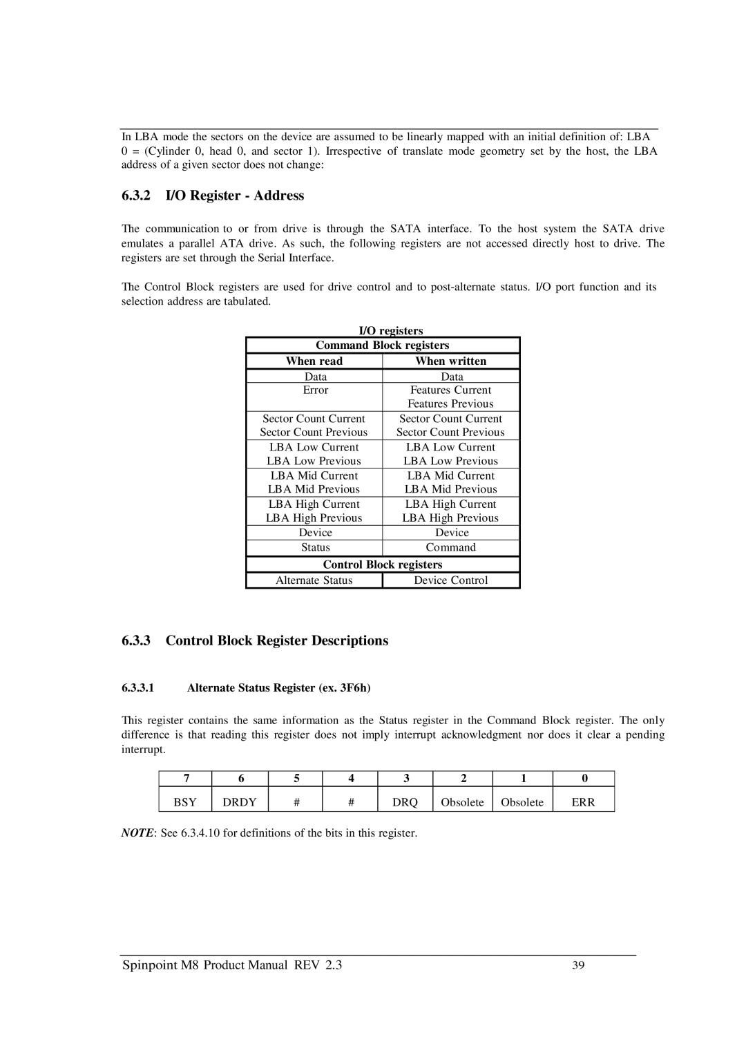
The communication to or from drive is through the SATA interface. To the host system the SATA drive emulates a parallel ATA drive. As such, the following registers are not accessed directly host to drive. The registers are set through the Serial Interface.
The Control Block registers are used for drive control and to
I/O registers | |
Command Block registers | |
When read | When written |
Data | Data |
Error | Features Current |
| Features Previous |
Sector Count Current | Sector Count Current |
Sector Count Previous | Sector Count Previous |
LBA Low Current | LBA Low Current |
LBA Low Previous | LBA Low Previous |
LBA Mid Current | LBA Mid Current |
LBA Mid Previous | LBA Mid Previous |
LBA High Current | LBA High Current |
LBA High Previous | LBA High Previous |
Device | Device |
Status | Command |
Control Block registers | |
Alternate Status | Device Control |
6.3.3Control Block Register Descriptions
6.3.3.1Alternate Status Register (ex. 3F6h)
This register contains the same information as the Status register in the Command Block register. The only difference is that reading this register does not imply interrupt acknowledgment nor does it clear a pending interrupt.
7 | 6 | 5 | 4 | 3 | 2 | 1 | 0 |
BSY | DRDY | # | # | DRQ | Obsolete | Obsolete | ERR |
|
|
|
|
|
|
|
|
NOTE: See 6.3.4.10 for definitions of the bits in this register.
Spinpoint M8 Product Manual REV 2.3 | 39 |
