6.3.3.2Device Control Register (ex. 3F6h)
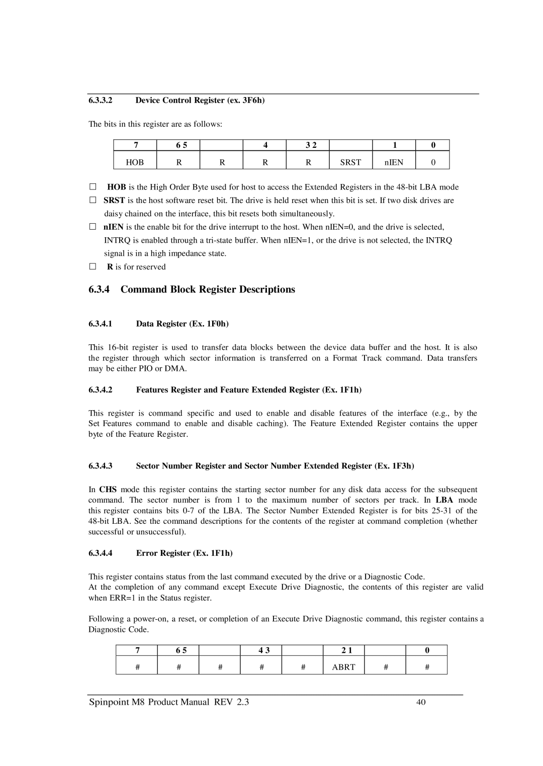
The bits in this register are as follows:
7 | 6 5 |
| 4 | 3 2 |
| 1 | 0 |
HOB | R | R | R | R | SRST | nIEN | 0 |
|
|
|
|
|
|
|
|
HOB is the High Order Byte used for host to access the Extended Registers in the
SRST is the host software reset bit. The drive is held reset when this bit is set. If two disk drives are daisy chained on the interface, this bit resets both simultaneously.
nIEN is the enable bit for the drive interrupt to the host. When nIEN=0, and the drive is selected, INTRQ is enabled through a
R is for reserved
6.3.4Command Block Register Descriptions
6.3.4.1Data Register (Ex. 1F0h)
This
6.3.4.2Features Register and Feature Extended Register (Ex. 1F1h)
This register is command specific and used to enable and disable features of the interface (e.g., by the Set Features command to enable and disable caching). The Feature Extended Register contains the upper byte of the Feature Register.
6.3.4.3Sector Number Register and Sector Number Extended Register (Ex. 1F3h)
In CHS mode this register contains the starting sector number for any disk data access for the subsequent command. The sector number is from 1 to the maximum number of sectors per track. In LBA mode this register contains bits
6.3.4.4Error Register (Ex. 1F1h)
This register contains status from the last command executed by the drive or a Diagnostic Code.
At the completion of any command except Execute Drive Diagnostic, the contents of this register are valid when ERR=1 in the Status register.
Following a
7 | 6 5 |
| 4 3 |
| 2 1 |
| 0 |
# | # | # | # | # | ABRT | # | # |
|
|
|
|
|
|
|
|
Spinpoint M8 Product Manual REV 2.3 | 40 |
