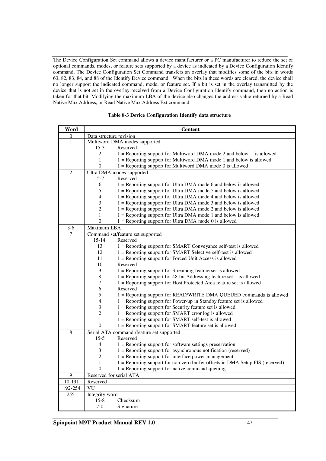
The Device Configuration Set command allows a device manufacturer or a PC manufacturer to reduce the set of optional commands, modes, or feature sets supported by a device as indicated by a Device Configuration Identify command. The Device Configuration Set Command transfers an overlay that modifies some of the bits in words 63, 82, 83, 84, and 88 of the Identify Device command. When the bits in these words are cleared, the device shall no longer support the indicated command, mode, or feature set. If a bit is set in the overlay transmitted by the device that is not set in the overlay received from a Device Configuration Identify command, then no action is taken for that bit. Modifying the maximum LBA of the device also changes the address value returned by a Read Native Max Address, or Read Native Max Address Ext command.
Table 8-3 Device Configuration Identify data structure
| Word |
|
| Content |
|
|
| 0 | Data structure revision |
|
| ||
| 1 | Multiword DMA modes supported |
|
| ||
|
| Reserved |
|
| ||
|
| 2 | 1 | = Reporting support for Multiword DMA mode 2 and below is allowed | ||
|
| 1 | 1 | = Reporting support for Multiword DMA mode 1 and below is allowed | ||
|
| 0 | 1 | = Reporting support for Multiword DMA mode 0 is allowed | ||
| 2 | Ultra DMA modes supported |
|
| ||
|
| Reserved |
|
| ||
|
| 6 | 1 | = Reporting support for Ultra DMA mode 6 and below is allowed | ||
|
| 5 | 1 | = Reporting support for Ultra DMA mode 5 and below is allowed | ||
|
| 4 | 1 | = Reporting support for Ultra DMA mode 4 and below is allowed | ||
|
| 3 | 1 | = Reporting support for Ultra DMA mode 3 and below is allowed | ||
|
| 2 | 1 | = Reporting support for Ultra DMA mode 2 and below is allowed | ||
|
| 1 | 1 | = Reporting support for Ultra DMA mode 1 and below is allowed | ||
|
| 0 | 1 | = Reporting support for Ultra DMA mode 0 is allowed |
|
|
| Maximum LBA |
|
|
| ||
| 7 | Command set/feature set supported |
|
| ||
|
| Reserved |
|
| ||
|
| 13 | 1 | = Reporting support for SMART Conveyance | ||
|
| 12 | 1 | = Reporting support for SMART Selective | ||
|
| 11 | 1 | = Reporting support for Forced Unit Access is allowed |
|
|
|
| 10 | Reserved |
|
| |
|
| 9 | 1 | = Reporting support for Streaming feature set is allowed | ||
|
| 8 | 1 | = Reporting support for | is allowed | |
|
| 7 | 1 | = Reporting support for Host Protected Area feature set is allowed | ||
|
| 6 | Reserved |
|
| |
|
| 5 | 1 | = Reporting support for READ/WRITE DMA QUEUED commands is allowed | ||
|
| 4 | 1 | = Reporting support for | ||
|
| 3 | 1 | = Reporting support for Security feature set is allowed |
|
|
|
| 2 | 1 | = Reporting support for SMART error log is allowed |
|
|
|
| 1 | 1 | = Reporting support for SMART |
|
|
|
| 0 | 1 | = Reporting support for SMART feature set is allowed |
|
|
| 8 | Serial ATA command /feature set supported |
|
| ||
|
| Reserved |
|
| ||
|
| 4 | 1 | = Reporting support for software settings preservation |
|
|
|
| 3 | 1 | = Reporting support for asynchronous notification (reserved) | ||
|
| 2 | 1 | = Reporting support for interface power management |
|
|
|
| 1 | 1 | = Reporting support for | ||
|
| 0 | 1 | = Reporting support for native command queuing |
|
|
| 9 | Reserved for serial ATA |
|
| ||
| Reserved |
|
|
|
| |
| VU |
|
|
|
| |
| 255 | Integrity word |
|
|
| |
|
| Checksum |
|
| ||
|
| Signature |
|
| ||
|
|
|
|
|
|
|
Spinpoint M9T Product Manual REV 1.0 | 47 |
| ||||
