SDS-V4040
Channel DVR
Channel DVR
Overview
Important Safety Instructions
Overview
System Shutdown
Before Start
Contents
Appendix
Backup viewer
Search & play
Web Viewer
Standards Approvals
Features
Package Contents
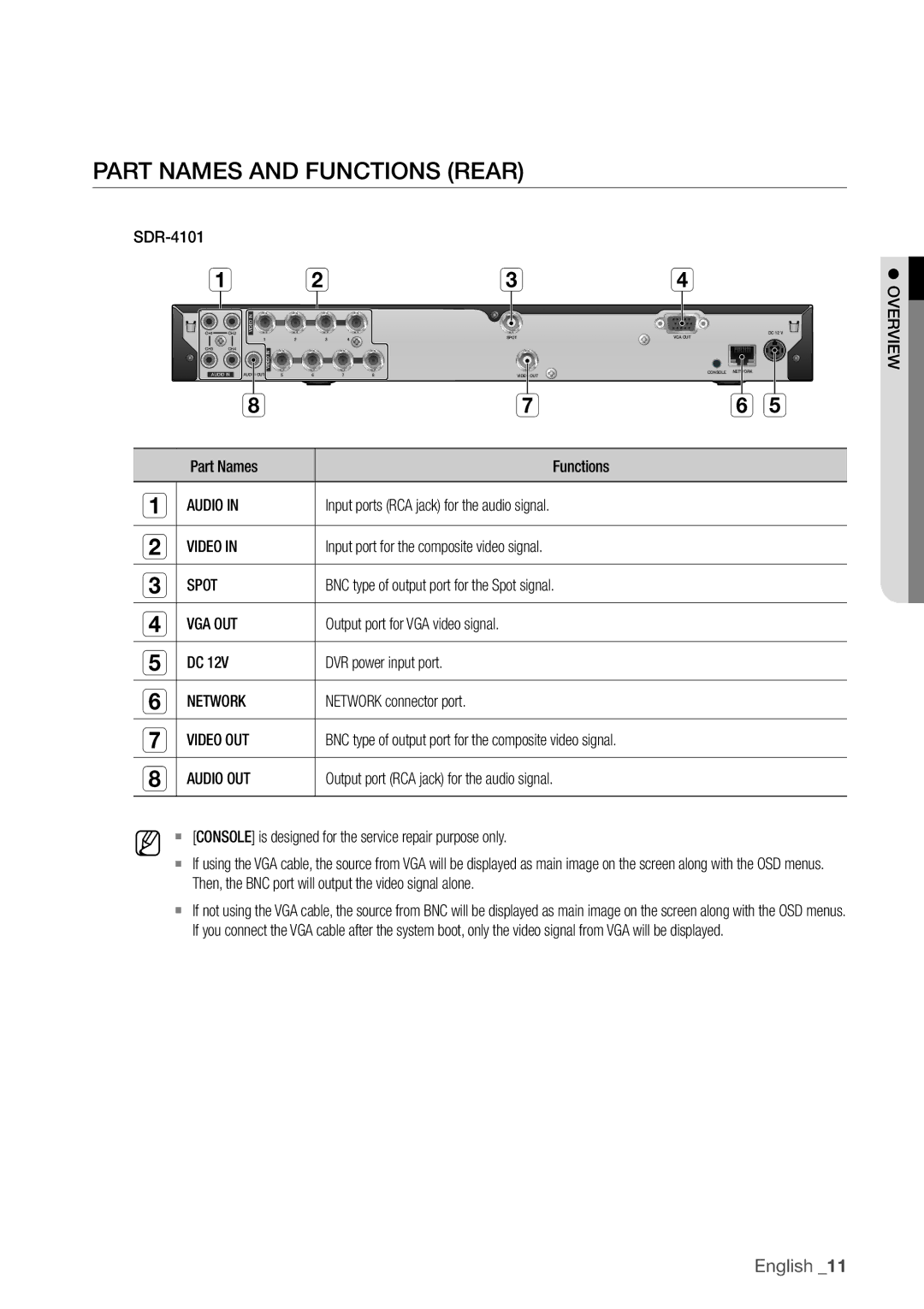
PArT nAmeS And funCTionS fronT
Input the remote control signal
Part Names and Functions Rear
Channel
Power
Changing the Remote Control ID
Checking the Installation Environment
Installation
OTher deviCe
ConneCTinG The video, Audio And moniTor
ConneCTinG The uSB
ConneCTinG wiTh
Lens
ConneCTinG The CAmerA SdC-5440BC
ConneCTinG wiTh oTher deviCe
Installing the camera
Connecting with dvr
Condensation
Connect the camera cable to the camera
Up with impurities
Ther htodevi wig in ct c !onne
Connecting the Network
Connecting to network through Ethernet 10/100BaseT
Connecting to Network through Adsl
Connecting to the Network using the router
Shutting down the System
GeTTinG STArTed
Starting the system
You will see the context sensitive menu as in the right
Login
Locking All Buttons
Live mode, right-click any area of the screen
Icons on the Live Screen
Live Screen Configuration
Live Screen menu
Error information
Shutdown Turns down the DVR
Split mode menu
Login/Logout You can log in or out Live
Record/Stop Starts/stops the standard recording Play
Zoom Enlarges the selected image.
Single mode menu
Single mode menu is available only in Single Mode
Menu Description Full Screen
View the Launcher menu
` The Launcher menu can be accessed only by using the mouse
Date/Time/Language Time. Screen Mode
Current mode is highlighted in white
Auto Sequence
Live Mode
Switching the screen mode
Switching the split mode
Manual Switching
Switching to Single Mode
Channel Setting
Zoom
Selecting a Spot out mode
SpoT ouT
Freeze
Audio On/Off in Single mode
Audio On/Off
Performed Live
Event Monitoring
Date/Time/Language
SYSTem SeTuP
Setting the Date/Time/Language
Press the menu button on the remote control
Screen
DST Set up Daylight Saving Time with its period to make
Date Sets the date that will appear on the screen
You can select the date format
Using the Calendar
Setting Holiday
Permission management
Setting the administrator
Using Virtual Keyboard
To set the group authority
Setting the Group
Select user menu
To change the user password
To restrict the user permissions
Main menu
When the user setup is done, press OK
Setting the user
Setting Permissions
Checking the System information
System management
Updating progresses with 3 steps as shown in the figure
Center for assistance
System Log
Settings
Log information
Event Log
Backup Log
Camera
SeTTinG THe DeViCe
Setting the Camera
To set the privacy region
When the camera setup is done, press OK
To set the area using individual selection
③ When completing the privacy zone settings, click OK
You can check information on storage devices
Storage Device
Confirming Devices
Select Format
Formatting
You can format a storage device
Remote Devices
HDD alarm
Monitor
Setting the monitor
Setting Display position
Setting the Screen mode
Setting the Spot Out
Recording Schedule
SeTTinG THe ReCORDinG
Recording Color Tags
Event Record Duration
When the Event recording setup is done, press OK
ReC Quality & Resolution
Setting Standard Recording Properties
Setting event Recording Properties
Full
Disk End Mode If selected Overwrite, recording will
Record Option
Motion Detection
SeTTinG THe eVenT
Setting the motion Detection area
③ When the motion detection setup is done, press OK
On Marked in orange, and always generates alarm on
Alarm Schedule
Window of alarm Schedule settings appears
Alarm.
You can backup the desired data to a connected device
BaCKuP
Setting the Backup
You can set the network connection route and protocol
NeTWORK COnFiGuRaTiOn
Connection mode
Setting the Connection
UDP
Setting the Protocol
DVR
Notification
Select one between 4505 and 4530 for Rtsp
Network Overview
2nd Set Port Forwarding Setting
1st Set Port Forwarding Setting
When no router is used
Connecting and Setting the network
When a router is used
Network
Internal Port Range Set the same to the external Port Range
English
Be displayed Type your set ID in Product iD field
` Refer to Using Virtual Keyboard.
When the Ddns setup is done, press OK
DDnS
IPOLiS DDnS Setting
DDnS Setting
Live Transfer
SmTP Setting
Mailing Service
Interval, not on each event
Event Setting
Group Setting
Set the value Event Interval Set the event interval
When the recipient setting is done, press OK
Recipient Setting
Time Search
SeaRCH
Hours
Detailed mode above
Event Search
Zoom In The map enlarges in detail
Motion Search
Backup Search
Play
@ button on the remote control
PLaYBaCK
M n
Using the Playback Button
System Requirements
What is Web Viewer?
Product Features
Introducing Web Viewer
Safari on MAc
Connecting Web VieWer MAc
USing liVe VieWer MAc
DVR into the URL address box
Connecting Web VieWer WindoWS
` All settings are applied by the DVR’s settings
Click install Activex control…
USing liVe VieWer WindoWS
Split-Screen
Single Mode Quad Mode
OSd information display
Connected dVr
Setting the display of the oSd time information
Changing the live Screen Mode
CAPture Saves the current screen into a BMP or Jpeg file
Saving the live Screen on the Pc
Button and then select
Changing the live Screen channel
USing SeArch VieWer
Exceeded
\users\user
Web Viewer\VideoClip\Search. To change the saving path
Searching the recorded Video in the timeline
Searching the recorded Video in the calendar
Check duplicates
Date/time/language
VieWer SetuP
System
Controlling Playback C d G h
Permission Management
Holiday
System Management
Camera
Device
Remote device
Storage device
Monitor
Event record duration
For more information, refer to Setting the recording.
Record
Recording Schedule
Motion detection
Rec Quality & resolution
Event
Record option
Motion region Set the target motion detection area
Alarm Schedule
You can set the alarm output time if a video loss occurs
Video loss detection
DdnS
For more information, refer to network configuration.
Network
Connection
Live transfer
Mailing Service
About
Mobile Viewer
What is Mobile Viewer?
Using a Smartphone
Compatible Smartphone
Key Features
Recommended System requirements
Sec bAcKuP VieWer
Between activated and deactivated
You can adjust the volume level from 0 to
You can enable the De-interlace function
Speed will restore to
Stop playing temporarily
SDC-5440BCN SDC-5440BCP
Product Specification Camera
NTSC120fps, PAL100fps Bandwidth
Product Specificationdvr
6, 8, 9, 13, PIP, Sequence
Recording
Hdmi
RTP, RTSP, HTTP, CGI
500GB Sata HDD
VGA
USB
Management
Default Setting
OFF
Category Details Factory Default
Duration
Smtp
Troubleshooting
On the screen
By the service personnel
Quick start guide backup, search
Icon on the launcher to switch to Live mode Endixapp
4CIF2CIFCIF
Preamble
Open Source License Report on the Product
GNU General Public License
END of Terms and Conditions
No Warranty
How to Apply These Terms to Your New Programs
Conveying Verbatim Copies
Terms and Conditions
Conveying Modified Source Versions
Acceptance Not Required for Having Copies
Limitation of Liability
GNU Lesser General Public License
Page
Original SSLeay License
How to Apply These Terms to Your New Libraries
OpenSSL License
Page
Correct disposal of batteries in this product
Page
Samsung Techwin America Inc
Sales Network