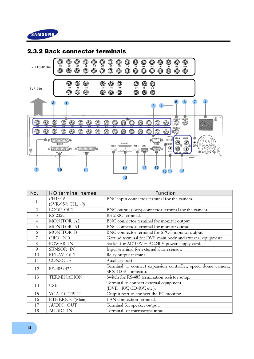
2.3.2 Back connector terminals
|
| 2 |
| 1 |
|
|
|
|
|
|
|
|
| 3 | 4 | 5 | 6 | 7 | 8 |
|
|
|
|
|
|
|
|
|
|
|
|
|
|
|
| ||||
|
|
|
|
|
|
|
|
|
|
|
|
|
|
|
|
|
| ||
|
|
|
|
|
|
|
|
|
|
|
|
|
|
|
| MONITOR A1 | MONITOR B |
|
|
CH1 | CH2 | CH3 | CH4 | CH5 | CH6 | CH7 | CH8 | CH9 | CH10 | CH11 | CH12 | CH13 | CH14 | CH15 | CH16 | MONITOR A2 |
|
|
|
|
|
|
|
|
|
|
|
|
|
|
|
|
|
|
|
|
|
| |
|
|
|
|
|
|
|
|
|
|
|
|
|
|
|
| AUDIO IN 1 | AUDIO IN 2 |
|
|
SENSOR IN
ETHERNET |
TERM 1 | TERM 2 | USB3,4 |
RELAY OUT | CONSOLE |
1 2 | 3 | 4 | 1 2 | 3 | 4 |
| AUDIO |
|
|
|
|
|
|
|
| VGA | AUDIO IN 3 | AUDIO IN 4 | |
|
|
|
|
|
| OUT | |||
|
|
|
|
|
|
|
9 | 10 | 11 | 12 | 14 | 15 | 18 |
|
| 16 17 | ||||
|
|
|
|
| ||
|
|
| 13 |
|
|
|
No. | I/O terminal names | Function | |
1 | CH1~16 | BNC input connector terminal for the camera. | |
| |||
|
| ||
2 | LOOP OUT | BNC output (loop) connector terminal for the camera. | |
3 | |||
4 | MONITOR A2 | BNC connector terminal for monitor output. | |
5 | MONITOR A1 | BNC connector terminal for monitor output. | |
6 | MONITOR B | BNC connector terminal for SPOT monitor output. | |
7 | GROUND | Ground terminal for DVR main body and external equipment. | |
8 | POWER IN | Socket for AC100V ~ AC240V power supply cord. | |
9 | SENSOR IN | Input terminal for external alarm sensor. | |
10 | RELAY OUT | Relay output terminal. | |
11 | CONSOLE | Auxiliary port | |
12 | Terminal to connect expansion controller, speed dome camera, | ||
|
| ||
13 | TERMINATION | Switch for | |
14 | USB | Terminal to connect external equipment | |
(DVD+RW, | |||
|
| ||
15 | VGA OUTPUT | Output port to connect the PC monitor. | |
16 | ETHERNET(Main) | LAN connection terminal. | |
17 | AUDIO OUT | Terminal for speaker output. | |
18 | AUDIO IN | Terminal for microscope input. |
14