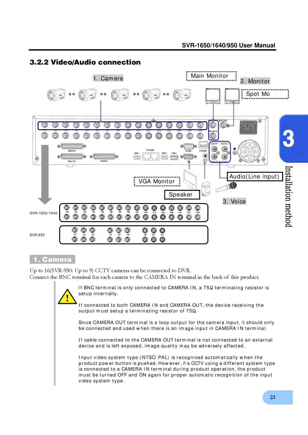
3.2.2 Video/Audio connection
| Main Monitor |
| |
1. Camera | |||
2. Monitor | |||
| |||
|
|
Spot Mo i
|
|
|
|
|
|
|
|
|
|
|
|
|
|
|
| MONITOR A1 | MONITOR B |
CH1 | CH2 | CH3 | CH4 | CH5 | CH6 | CH7 | CH8 | CH9 | CH10 | CH11 | CH12 | CH13 | CH14 | CH15 | CH16 | MONITOR A2 |
|
|
|
|
|
|
|
|
|
|
|
|
|
|
|
|
|
| |
|
|
|
|
|
|
|
|
|
|
|
|
|
|
|
| AUDIO IN 1 | AUDIO IN 2 |
|
|
| SENSOR IN |
|
|
|
|
| TERM 1 |
| TERM 2 |
| USB3,4 | ETHERNET |
|
| |
|
|
|
|
|
|
|
|
|
|
|
|
|
|
| |||
|
|
|
|
|
|
|
|
| 1 2 3 4 |
| 1 2 3 4 |
|
|
| AUDIO |
|
|
|
|
| RELAY OUT |
|
| CONSOLE |
|
|
|
|
|
|
| VGA | AUDIO IN 3 | AUDIO IN 4 | |
|
|
|
|
|
|
|
|
|
|
|
| OUT |
3
VGA Monitor
Speaker

 Audio(Line input)

3. Voice
1. Camera
Up to
Connect the BNC terminal for each camera to the CAMERA IN terminal in the back of this product.
If BNC terminal is only connected to CAMERA IN, a 75Ω terminating resistor is setup internally.
If connected to both CAMERA IN and CAMERA OUT, the device receiving the output must setup a terminating resistor of 75Ω.
Since CAMERA OUT terminal is a loop output for the camera input, it should only be connected and used when there is an image input in CAMERA IN terminal.
If cable connected to the CAMERA OUT terminal is not connected to an external device and is left exposed, image quality may be adversely affected.
Input video system type (NTSC/PAL) is recognized automatically when the product power button is pushed. However, if a CCTV using a different system type is connected to a CAMERA IN terminal during product operation, the product must be turned OFF and ON again for proper automatic recognition of the input video system type .
23