3-8. Wiring Instructions for Inter-unit Connections
(1)Insert the
(2)Grasp both ends of the front panel, push the arms towards the outside, and remove the front panel by opening it towards the front and pulling it towards you. If the front panel is difficult to remove, grasp both ends of it and lift it up slightly. Move it to the left and disengage the left arm, then move it to the right and disengage the right arm.
(3)Remove the screw on the right side cover plate and open the cover. (Fig. 25)
(4)Route the
(5)Connect the
(6)Be sure to secure the wiring with the provided clamp.
NOTE
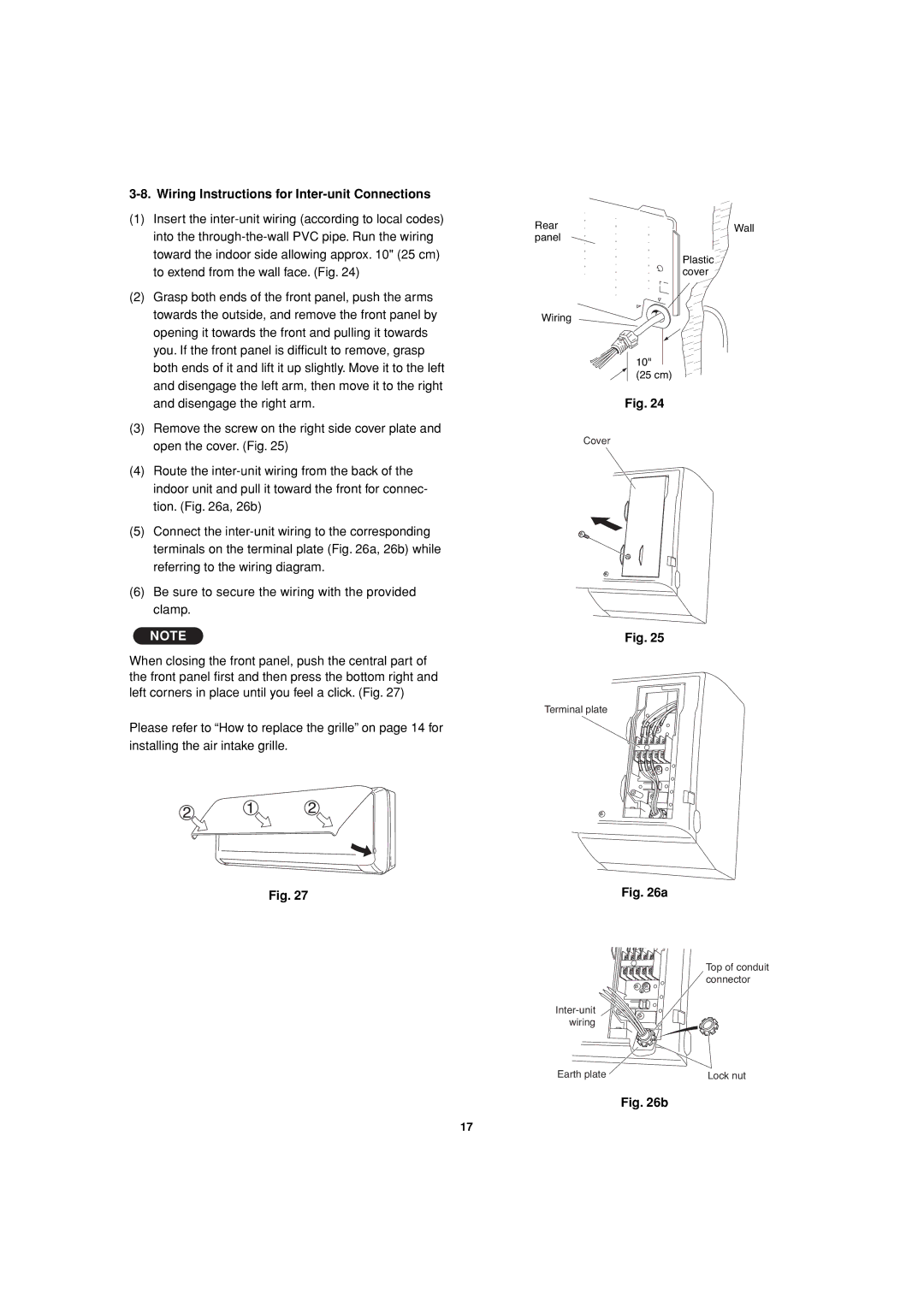
When closing the front panel, push the central part of the front panel first and then press the bottom right and left corners in place until you feel a click. (Fig. 27)
Please refer to “How to replace the grille” on page 14 for installing the air intake grille.
Fig. 27
Rear | Wall |
panel |
|
Plastic ![]()
![]() cover
cover ![]()
Wiring
10"
(25 cm)
Fig. 24
Cover
Fig. 25
Terminal plate
Fig. 26a
| Top of conduit |
| connector |
| |
wiring |
|
Earth plate | Lock nut |
Fig. 26b
17