LA6548ND
Overview
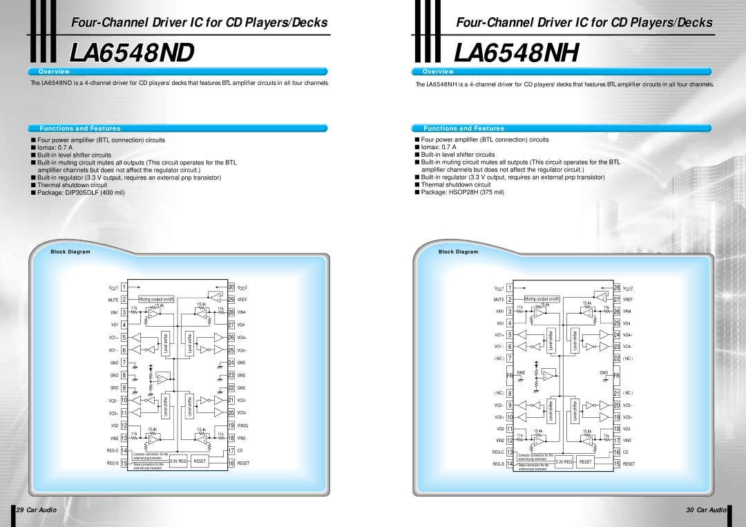
The LA6548ND is a
Functions and Features
■Four power amplifier (BTL connection) circuits
■Iomax: 0.7 A
■
■
■
■Thermal shutdown circuit
■Package: DIP30SDLF (400 mil)
Block Diagram
VCC1 | 1 |
|
|
|
|
| 30 | VCC2 |
| 2 |
|
|
|
| - | 29 |
|
MUTE |
| Muting (output on/off) |
| 15.4k | + | VREF | ||
|
| 11k | 15.4k |
| 11k |
|
| |
|
|
|
|
|
| |||
VIN1 | 3 | - |
| - | 28 | VIN4 | ||
|
| |||||||
|
|
| + |
| + |
|
|
|
VG1 | 4 |
|
|
|
|
| 27 | VG4 |
VO1+ | 5 |
| Level shifter | Level shifter |
|
| 26 | VO4+ |
VO1- | 6 |
|
|
| 25 | VO4- | ||
GND | 7 |
|
|
|
|
| 24 | GND |
GND | 8 |
| - |
|
|
| 23 | GND |
|
|
| + |
|
|
|
|
|
GND | 9 |
|
|
|
|
| 22 | GND |
VO2- | 10 |
| Level shifter | Level shifter |
|
| 21 | VO3- |
VO2+ | 11 |
|
|
| 20 | VO3+ | ||
VG2 | 12 |
| 15.4k |
| 15.4k |
| 19 | VIN3G |
|
| 11k |
| 11k |
|
| ||
VIN2 | 13 | - |
| - | 18 | VIN3 | ||
|
|
| ||||||
|
|
| + |
| + |
|
|
|
14 | Collector connection for the |
|
|
| 17 | CD | ||
|
|
|
|
|
|
| ||
|
| external pnp transistor |
| RESET |
|
|
| |
15 |
| 3.3V REG |
|
| 16 | RESET | ||
Base connection for the |
|
|
| |||||
|
| external pnp transistor |
|
|
|
|
| |
LA6548NHNH
Overview
The LA6548NH is a
Functions and Features
■Four power amplifier (BTL connection) circuits
■Iomax: 0.7 A
■
■
■
■Thermal shutdown circuit
■Package: HSOP28H (375 mil)
Block Diagram
VCC1 | 1 |
|
|
|
| 28 | VCC2 |
| 2 |
|
|
| - | 27 |
|
MUTE | Muting (output on/off) |
| + | VREF | |||
|
| 11k | 15.4k |
| 15.4k |
|
|
|
|
| 11k |
|
| ||
VIN1 | 3 |
|
| 26 | VIN4 | ||
| - |
| - | ||||
|
|
| + |
| + |
|
|
VG1 | 4 |
|
|
|
| 25 | VG4 |
VO1+ | 5 |
| Level shifter | Level shifter |
| 24 | VO4+ |
VO1- | 6 |
|
| 23 | VO4- | ||
( NC ) | 7 |
|
|
|
| 22 | ( NC ) |
| FR | GND | - |
| GND | FR |
|
|
| + |
|
|
| ||
( NC ) | 8 |
|
|
|
| 21 | ( NC ) |
VO2- | 9 |
| Level shifter | Level shifter |
| 20 | VO3- |
VO2+ | 10 |
|
| 19 | VO3+ | ||
VG2 | 11 |
| 15.4k |
| 15.4k | 18 | VG3 |
|
| 11k |
|
|
| ||
| 12 | - |
| 11k | 17 |
| |
VIN2 |
|
| - | VIN3 | |||
| + |
| + | ||||
13 | Collector connection for the |
|
| 16 | CD | ||
|
|
|
|
|
| ||
|
| external pnp transistor |
| RESET |
|
| |
14 |
| 3.3V REG |
| 15 | RESET | ||
Base connection for the |
|
| |||||
|
| external pnp transistor |
|
|
|
| |
| 29 Car Audio | 30 Car Audio |
|
|
|
