Power Amplifier
LA47510
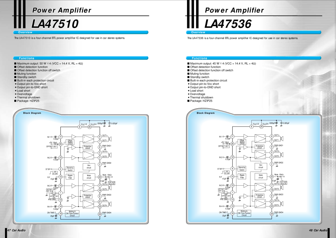
Overview
The LA47510 is a
Functions
■Maximum output: 50 W ![]() 4 (VCC = 14.4 V, RL = 4Ω )
4 (VCC = 14.4 V, RL = 4Ω )
■Offset detection function
■Offset detection function off switch
■Muting function
■Standby switch
■
◆Output
◆Output
◆Load short
◆Overvoltage
◆Thermal shutdown
■Package: HZIP25
Block Diagram
|
|
|
|
|
|
| + |
|
|
|
|
| VCC1/2 | VCC3/4 2200∝F | 0.022∝F | ||
|
|
| 6 | 20 |
|
|
|
|
IN 1 | + | 11 |
| + | + | 9 | OUT1+ |
|
0.22∝F | Offset |
| OUT1- |
| ||||
+5V 10kΩ |
| - | - | 7 |
| |||
25 | Detect |
|
| |||||
OFFSET DET | Circuit | Protective |
| PWR GND1 |
| |||
|
| 8 |
| |||||
|
|
|
| |||||
|
|
|
| circuit |
|
|
|
|
|
|
|
| - | + | 5 | OUT2+ |
|
|
|
|
|
|
| |||
IN 2 | + | 12 |
| + | - | 3 | OUT2- |
|
0.22∝F |
|
|
| |||||
|
|
|
|
|
|
|
| |
|
|
|
| Aux |
| 2 | PWR GND2 |
|
|
|
|
|
|
|
| ||
|
|
|
|
|
|
|
| |
ST BY |
| 4 | Stand by | circuit |
|
|
| |
| Switch |
|
|
|
|
| ||
| +5V |
|
|
|
|
|
| |
|
|
|
|
|
|
|
| |
| ST ON |
| Ripple | Mute |
| Mute 10kΩ |
| |
R.F | + | 10 | 22 |
| ||||
Filter | circuit | + |
| |||||
| 47∝F |
|
|
|
| 3.3∝F |
| |
|
|
|
|
|
|
| ||
|
|
|
|
| + |
| Low Level | |
IN 3 | + | 15 |
| + | 17 | OUT3+ Mute ON | ||
0.22∝F |
|
| OUT3- |
| ||||
OFFSET DET |
|
| - | - | 19 |
| ||
OFF S.W | 1 |
|
|
| ||||
| GND |
|
|
|
| PWR GND3 |
| |
|
|
| Protective | 8 |
| |||
OFFSET DET |
|
|
|
| ||||
| OFF | 13 |
| circuit |
|
|
|
|
PRE GND |
| - | + | 21 | OUT4+ |
| ||
|
|
|
|
| ||||
IN 4 | + | 14 |
| + | - | 23 | OUT4- |
|
| 0.22∝F |
|
|
|
|
|
|
|
ON TIME C + | 16 | Muting & |
|
|
| PWR GND4 |
| |
ON Time Control |
|
| 24 |
| ||||
| 22∝F |
| Circuit |
|
|
|
|
|
Power Amplifierplifier
LA4753636
Overview
The LA47536 is a
Functions
■Maximum output: 45 W ![]() 4 (VCC = 14.4 V, RL = 4Ω )
4 (VCC = 14.4 V, RL = 4Ω )
■Offset detection function
■Offset detection function off switch
■Muting function
■Standby switch
■
◆Output
◆Output
◆Load short
◆Overvoltage
◆Thermal shutdown
■Package: HZIP25
Block Diagram
|
|
|
|
|
|
| + |
|
|
|
|
| VCC1/2 | VCC3/4 2200∝F | 0.022∝F | ||
|
|
| 6 | 20 |
|
|
|
|
IN 1 | + | 11 |
| + | + | 9 | OUT1+ |
|
0.22∝F | Offset |
| OUT1- |
| ||||
+5V 10kΩ |
| - | - | 7 |
| |||
25 | Detect |
|
| |||||
OFFSET DET | Circuit | Protective |
| PWR GND1 |
| |||
|
| 8 |
| |||||
|
|
|
| |||||
|
|
|
| circuit |
|
|
|
|
|
|
|
| - | + | 5 | OUT2+ |
|
|
|
|
|
|
| |||
IN 2 | + | 12 |
| + | - | 3 | OUT2- |
|
0.22∝F |
|
|
| |||||
|
|
|
|
|
|
|
| |
|
|
|
| Aux |
| 2 | PWR GND2 |
|
|
|
|
|
|
|
| ||
|
|
|
|
|
|
|
| |
ST BY |
| 4 | Stand by | circuit |
|
|
| |
| Switch |
|
|
|
|
| ||
| +5V |
|
|
|
|
|
| |
|
|
|
|
|
|
|
| |
| ST ON |
| Ripple | Mute |
| Mute 10kΩ |
| |
R.F | + | 10 | 22 |
| ||||
Filter | circuit | + |
| |||||
| 47∝F |
|
|
|
| 3.3∝F |
| |
|
|
|
|
|
|
| ||
|
|
|
|
| + |
| Low Level | |
IN 3 | + | 15 |
| + | 17 | OUT3+ Mute ON | ||
0.22∝F |
|
| OUT3- |
| ||||
OFFSET DET |
|
| - | - | 19 |
| ||
OFF S.W | 1 |
|
|
| ||||
| GND |
|
|
|
| PWR GND3 |
| |
|
|
| Protective | 8 |
| |||
OFFSET DET |
|
|
|
| ||||
| OFF | 13 |
| circuit |
|
|
|
|
PRE GND |
| - | + | 21 | OUT4+ |
| ||
|
|
|
|
| ||||
IN 4 | + | 14 |
| + | - | 23 | OUT4- |
|
| 0.22∝F |
|
|
|
|
|
|
|
ON TIME C + | 16 | Muting & |
|
|
| PWR GND4 |
| |
ON Time Control |
|
| 24 |
| ||||
| 22∝F |
| Circuit |
|
|
|
|
|
| 47 Car Audio | 48 Car Audio |
|
|
|