APPENDIX
CONFIGURATIONS OF TERMINALS
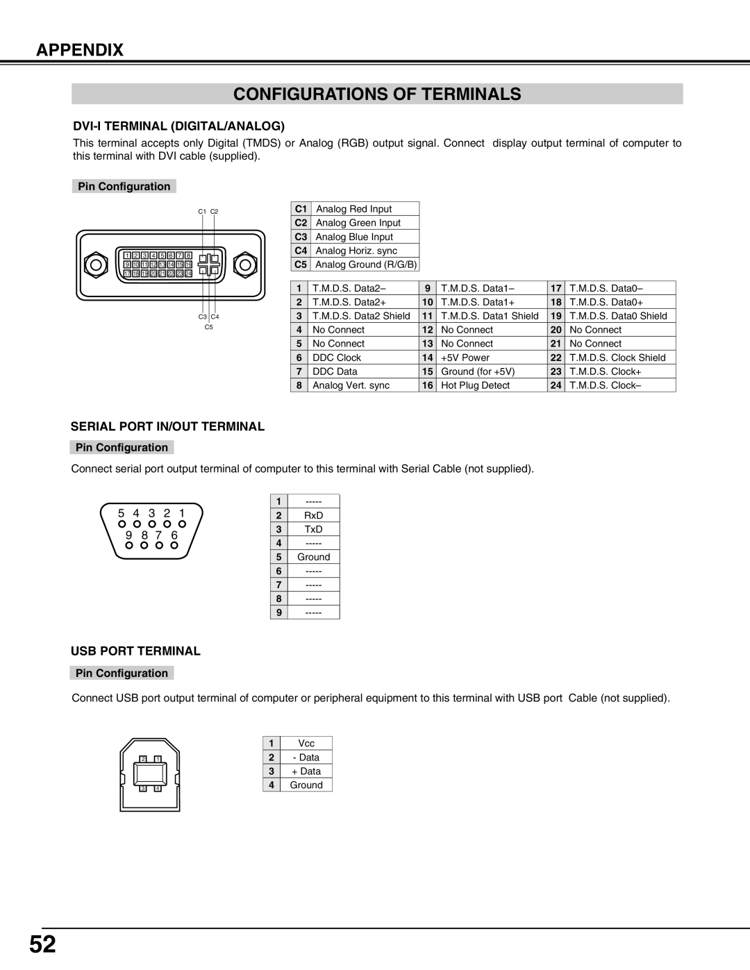
DVI-I TERMINAL (DIGITAL/ANALOG)
This terminal accepts only Digital (TMDS) or Analog (RGB) output signal. Connect display output terminal of computer to this terminal with DVI cable (supplied).
Pin Configuration
C1 C2
![]() 1
1 ![]()
![]() 2
2 ![]()
![]() 3
3 ![]()
![]() 4
4 ![]()
![]() 5
5 ![]()
![]() 6
6 ![]()
![]() 7
7 ![]()
![]() 8
8 ![]()
![]() 9
9 ![]()
![]() 10
10![]()
![]() 11
11![]()
![]() 12
12![]()
![]() 13
13![]()
![]() 14
14![]()
![]() 15
15![]()
![]() 16
16![]()
![]() 17
17![]()
![]() 18
18![]()
![]() 19
19![]()
![]() 20
20![]()
![]() 21
21![]()
![]() 22
22![]()
![]() 23
23![]()
![]() 24
24![]()
C3 C4
C5
| C1 | Analog Red Input |
|
|
|
|
| C2 | Analog Green Input |
|
|
|
|
| C3 | Analog Blue Input |
|
|
|
|
| C4 | Analog Horiz. sync |
|
|
|
|
| C5 | Analog Ground (R/G/B) |
|
|
|
|
|
|
|
|
|
|
|
| 1 | T.M.D.S. Data2– | 9 | T.M.D.S. Data1– | 17 | T.M.D.S. Data0– |
| 2 | T.M.D.S. Data2+ | 10 | T.M.D.S. Data1+ | 18 | T.M.D.S. Data0+ |
| 3 | T.M.D.S. Data2 Shield | 11 | T.M.D.S. Data1 Shield | 19 | T.M.D.S. Data0 Shield |
| 4 | No Connect | 12 | No Connect | 20 | No Connect |
| 5 | No Connect | 13 | No Connect | 21 | No Connect |
| 6 | DDC Clock | 14 | +5V Power | 22 | T.M.D.S. Clock Shield |
| 7 | DDC Data | 15 | Ground (for +5V) | 23 | T.M.D.S. Clock+ |
| 8 | Analog Vert. sync | 16 | Hot Plug Detect | 24 | T.M.D.S. Clock– |
SERIAL PORT IN/OUT TERMINAL
Pin Configuration
Connect serial port output terminal of computer to this terminal with Serial Cable (not supplied).
5 | 4 |
| 3 | 2 | 1 | 1 | |
| 2 | RxD | |||||
| 9 | 8 | 7 |
| 6 | 3 | TxD |
|
| 4 | |||||
|
|
|
|
|
| ||
|
|
|
|
|
| 5 | Ground |
|
|
|
|
|
| 6 | |
|
|
|
|
|
| 7 | |
|
|
|
|
|
| 8 | |
|
|
|
|
|
| 9 |
USB PORT TERMINAL
Pin Configuration
Connect USB port output terminal of computer or peripheral equipment to this terminal with USB port Cable (not supplied).
| 2 |
|
|
| 1 |
|
| 3 |
|
|
| 4 |
|
|
|
|
|
1Vcc
2- Data
3+ Data
4Ground
52