− 13 −
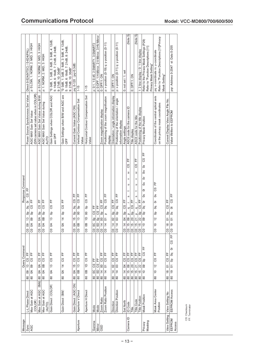
Message |
|
|
| Query Command |
|
|
|
|
| Response Command |
|
|
|
|
| |||||||
Sync | 80 | 09 | 13 | CS | FF |
| C0 | 09 | 13 | 0p | 0q | 0r | CS | FF |
|
|
|
|
| Power Source Synchronous Set Value | Direct | |
AGC | Max Gain at AGC | 80 | 0A | 09 | CS | FF |
| C0 | 0A | 09 | 0p | CS | FF |
|
|
|
|
|
|
| AGC MAX Gain Set Value | p: 0:LOW, 1: NORM, 2: MID, 3: HIGH |
| (COLOR) |
|
|
|
|
|
|
|
|
|
|
|
|
|
|
|
|
|
|
| (D/N camera set value when in COLOR) |
|
|
|
|
|
|
|
|
|
|
|
|
|
|
|
|
|
|
|
|
|
|
|
|
| Max Gain at AGC(BW) | 80 | 0A | 0A | CS | FF |
| C0 | 0A | 0A | 0p | CS | FF |
|
|
|
|
|
|
| AGC MAX Gain Set Value during B/W | p: 0:LOW, 1: NORM, 2: MID, 3: HIGH |
| Max Gain at AGC | 80 | 0A | 0B | CS | FF |
| C0 | 0A | 0B | 0p | CS | FF |
|
|
|
|
|
|
| AGC MAX Gain Set Value during | p: 1: NORM, 2: MID, 3: HIGH |
| (AUTO) |
|
|
|
|
|
|
|
|
|
|
|
|
|
|
|
|
|
|
| AUTO |
|
|
|
|
|
|
|
|
|
|
|
|
|
|
|
|
|
|
|
|
|
|
|
|
| Gain Direct(COLOR) | 80 | 0A | 13 | CS | FF |
| C0 | 0A | 13 | 0p | CS | FF |
|
|
|
|
|
|
| Gain Settings when COLOR and AGC | "0: 0dB, 1: 3dB, 2: 6dB, 3: 9dB, 4: 12dB, |
|
|
|
|
|
|
|
|
|
|
|
|
|
|
|
|
|
|
|
|
| are OFF | 5: 15dB, 6: 18dB, 7: 21dB, 8: 24dB, |
|
|
|
|
|
|
|
|
|
|
|
|
|
|
|
|
|
|
|
|
|
| 9: 27dB, 10: 30dB" |
|
|
|
|
|
|
|
|
|
|
|
|
|
|
|
|
|
|
|
|
|
|
|
| Gain Direct(BW) | 80 | 0A | 14 | CS | FF |
| C0 | 0A | 14 | 0p | CS | FF |
|
|
|
|
|
|
| Gain Settings when B/W and AGC are | "0: 0dB, 1: 3dB, 2: 6dB, 3: 9dB, 4: 12dB, |
|
|
|
|
|
|
|
|
|
|
|
|
|
|
|
|
|
|
|
|
| OFF | 5: 15dB, 6: 18dB, 7: 21dB, 8: 24dB, |
|
|
|
|
|
|
|
|
|
|
|
|
|
|
|
|
|
|
|
|
|
| 9: 27dB, 10: 30dB" |
|
|
|
|
|
|
|
|
|
|
|
|
|
|
|
|
|
|
|
|
|
|
|
| Gain Direct(AGC ON) | 80 | 0A | 15 | CS | FF |
| C0 | 0A | 15 | 0p | 0q | CS | FF |
|
|
|
|
|
| Current Gain Value (AGC ON) | pq: |
Aperture | Aperture V Direct | 80 | 0B | 13 | CS | FF |
| C0 | 0B | 13 | 00 | 0p | CS | FF |
|
|
|
|
|
| Vertical Contour Compensation Set | |
|
|
|
|
|
|
|
|
|
|
|
|
|
|
|
|
|
|
|
|
| Value |
|
|
|
|
|
|
|
|
|
|
|
|
|
|
|
|
|
|
|
|
|
|
|
|
| Aperture H Direct | 80 | 0B | 1D | CS | FF |
| C0 | 0B | 1D | 00 | 0p | CS | FF |
|
|
|
|
|
| Horizontal Contour Compensation Set | |
|
|
|
|
|
|
|
|
|
|
|
|
|
|
|
|
|
|
|
|
| Value |
|
|
|
|
|
|
|
|
|
|
|
|
|
|
|
|
|
|
|
|
|
| ||
Gamma | Mode | 80 | 0C | CS FF |
|
| C0 | 0C | 0p | CS FF |
|
|
|
|
|
|
|
|
| p: 0:1, 1:0.45, 2:SMART1, 3:SMART2 | ||
Mirror | Mode | 80 | 0D | CS FF |
|
| C0 | 0D | 0p | CS FF |
|
|
|
|
|
|
|
|
| p: 0:OFF, | ||
OSD | Zoom Ratio | 80 | 14 | 00 | CS | FF |
| C0 | 14 | 00 | 0p | CS | FF |
|
|
|
|
|
|
| Zoom magnification display | 0: OFF/1: ON |
| Zoom Ratio Position | 80 | 14 | 01 | CS | FF |
| C0 | 14 | 01 | p | 0q | CS | FF |
|
|
|
|
|
| Positioning of the zoom magnification | p: |
|
|
|
|
|
|
|
|
|
|
|
|
|
|
|
|
|
|
|
|
| display |
|
|
|
|
|
|
|
|
|
|
|
|
|
|
|
|
|
|
|
|
|
|
|
|
| Direction | 80 | 14 | 02 | CS | FF |
| C0 | 14 | 02 | 0p | CS | FF |
|
|
|
|
|
|
| Orientation / angle information display | 0: OFF/1: ON |
| Direction Position | 80 | 14 | 03 | CS | FF |
| C0 | 14 | 03 | 0p | 0q | CS | FF |
|
|
|
|
|
| Positioning of the orientation / angle | p: |
|
|
|
|
|
|
|
|
|
|
|
|
|
|
|
|
|
|
|
|
| information display |
|
|
|
|
|
|
|
|
|
|
|
|
|
|
|
|
|
|
|
|
|
|
|
|
| Set North | 80 | 14 | 04 | CS | FF |
| C0 | 14 | 04 | 0p | CS | FF |
|
|
|
|
|
|
| Angle settings | 0: not set / 1: set |
Camera ID | ID Code | 80 | 15 | 09 | CS | FF |
| C0 | 15 | 09 | p | q | r | s | t | u | v | w | CS | FF | ASCII code for the camera ID | (Note 5) |
| Title | 80 | 15 | 20 | CS | FF |
| C0 | 15 | 20 | 0p | CS | FF |
|
|
|
|
|
|
| Title display | 0: OFF/1: ON |
| Title Code | 80 | 15 | 21 | CS | FF |
| C0 | 15 | 21 | p | q | r | s | t | u | v | w | CS | FF | ASCII code for the title | (Note 5) |
| Title Position | 80 | 15 | 22 | CS | FF |
| C0 | 15 | 22 | 0p | CS | FF |
|
|
|
|
|
|
| Positioning of the title display | 1: 2 line display / 0: 1 line display |
Privacy | Mask Position | 80 | 10 | 09 | 0p | CS | FF | C0 | 10 | 09 | 0p | 0q | 0r | 0s | 0t | 0u | 0v | 0w | 0x | CS FF | Privacy Mask Position | Refer to the Privacy Mask Settings (P29) |
Masking |
|
|
|
|
|
|
|
|
|
|
|
|
|
|
|
|
|
|
|
|
| Refer to "Function Descriptions [11] |
|
|
|
|
|
|
|
|
|
|
|
|
|
|
|
|
|
|
|
|
|
| Privacy Mask Setting" |
|
|
|
|
|
|
|
|
|
|
|
|
|
|
|
|
|
|
|
|
|
|
|
| Mask Area Center | 80 | 10 | 12 | CS | FF |
| C0 | 10 | 12 | 0p | 0q | 0r | 0s | CS | FF |
|
|
|
| Coordinates of the central optical axis | pq: |
| Position |
|
|
|
|
|
|
|
|
|
|
|
|
|
|
|
|
|
|
| on the privacy mask coordinates | Refer to "Function Descriptions [11]Privacy |
|
|
|
|
|
|
|
|
|
|
|
|
|
|
|
|
|
|
|
|
|
| Mask Setting" |
|
|
|
|
|
|
|
|
|
|
|
|
|
|
|
|
|
|
|
|
|
|
|
View Setting | View Setting No | 80 | 18 | 01 | CS | FF |
| C0 | 18 | 01 | 0p | CS | FF |
|
|
|
|
|
|
| Current Display View Angle File No. |
|
EEPROM | EEPROM Access | 80 | 19 | 01 | 0p | 0q | 0r CS FF | C0 | 19 | 01 | 0s | 0t | CS | FF |
|
|
|
|
|
| Value Written to EEPROM | pqr: Address |
Access |
|
|
|
|
|
|
|
|
|
|
|
|
|
|
|
|
|
|
|
|
|
|
|
|
|
|
|
|
|
|
|
|
|
|
|
|
|
|
|
|
|
|
|
|
|
CS: Checksum
FF: Terminator
Communications Protocol
Model: