Input-Output Terminal Descriptions
[1] Input-Output Terminal Layout and Specifications
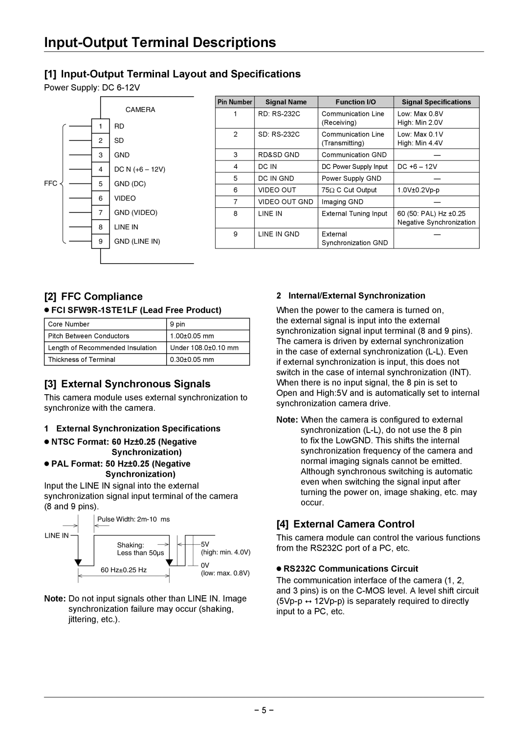
Power Supply: DC 6-12V
FFC
1
2
3
4
5
6
7
8
9
CAMERA
RD
SD
GND
DC N (+6 – 12V) GND (DC)
VIDEO
GND (VIDEO)
LINE IN
GND (LINE IN)
Pin Number | Signal Name | Function I/O | Signal Specifications |
1 | RD: | Communication Line | Low: Max 0.8V |
|
| (Receiving) | High: Min 2.0V |
2 | SD: | Communication Line | Low: Max 0.1V |
|
| (Transmitting) | High: Min 4.4V |
3 | RD&SD GND | Communication GND | — |
4 | DC IN | DC Power Supply Input | DC +6 – 12V |
|
|
|
|
5 | DC IN GND | Power Supply GND | — |
|
|
|
|
6 | VIDEO OUT | 75Ω C Cut Output | |
|
|
|
|
7 | VIDEO OUT GND | Imaging GND | — |
8 | LINE IN | External Tuning Input | 60 (50: PAL) Hz ±0.25 |
|
|
| Negative Synchronization |
9 | LINE IN GND | External | — |
|
| Synchronization GND |
|
[2] FFC Compliance
⁃⁃ FCI SFW9R-1STE1LF (Lead Free Product)
Core Number | 9 pin |
Pitch Between Conductors | 1.00±0.05 mm |
Length of Recommended Insulation | Under 108.0±0.10 mm |
|
|
Thickness of Terminal | 0.30±0.05 mm |
|
|
[3] External Synchronous Signals
This camera module uses external synchronization to synchronize with the camera.
1 External Synchronization Specifications
⁃⁃ NTSC Format: 60 Hz±0.25 (Negative
Synchronization)
⁃⁃ PAL Format: 50 Hz±0.25 (Negative
Synchronization)
Input the LINE IN signal into the external synchronization signal input terminal of the camera (8 and 9 pins).
Pulse Width:
LINE IN
Shaking: |
| 5V |
Less than 50µs |
| (high: min. 4.0V) |
60 Hz±0.25 Hz |
| 0V |
| ||
| (low: max. 0.8V) | |
|
|
Note: Do not input signals other than LINE IN. Image synchronization failure may occur (shaking, jittering, etc.).
2 Internal/External Synchronization
When the power to the camera is turned on, the external signal is input into the external synchronization signal input terminal (8 and 9 pins). The camera is driven by external synchronization in the case of external synchronization
Note: When the camera is configured to external synchronization
[4] External Camera Control
This camera module can control the various functions from the RS232C port of a PC, etc.
⁃⁃ RS232C Communications Circuit
The communication interface of the camera (1, 2, and 3 pins) is on the
− 5 −