How to wire the remote controller

(1)

Turn OFF the power and remove the ceiling panel


air-intake grille. (Refer to 3-6-1 Before Installing the


Ceiling Panel in the Installation Instructions supplied


with the indoor unit.)

(2)

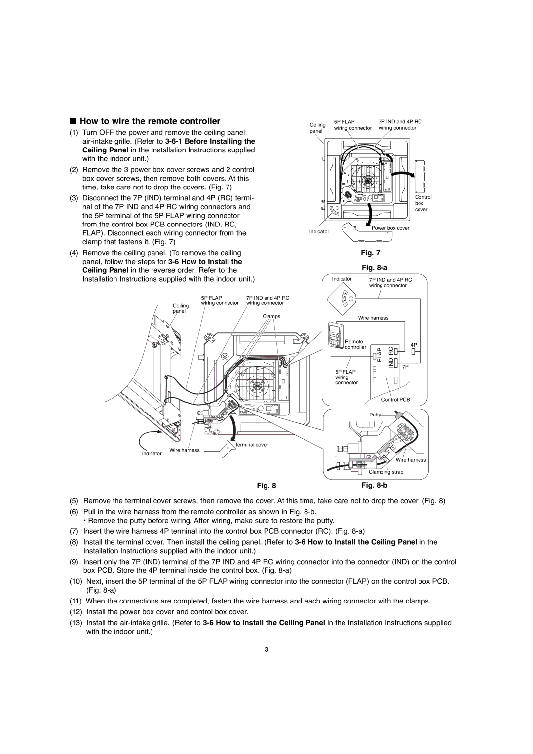
Remove the 3 power box cover screws and 2 control


box cover screws, then remove both covers. At this


time, take care not to drop the covers. (Fig. 7)

Ceiling


5P FLAP


7P IND and 4P RC


wiring connector


wiring connector

panel


(3) Disconnect the 7P (IND) terminal and 4P (RC) termi-

nal of the 7P IND and 4P RC wiring connectors and

the 5P terminal of the 5P FLAP wiring connector

from the control box PCB connectors (IND, RC,

FLAP). Disconnect each wiring connector from the

clamp that fastens it. (Fig. 7)

Indicator

Control box cover

Power box cover

(4) Remove the ceiling panel. (To remove the ceiling

panel, follow the steps for 3-6 How to Install the

Ceiling Panel in the reverse order. Refer to the

Installation Instructions supplied with the indoor unit.)


5P FLAP


7P IND and 4P RC


Ceiling

wiring connector


wiring connector


panel


Clamps


Fig. 7


Fig. 8-a


Indicator


7P IND and 4P RC


wiring connector


Wire harness


Remote


4P

controller


FLAP

IND RC


5P FLAP


7P


wiring


connector


Control PCB


Putty


Terminal cover

Wire harness

Indicator

Wire harness

Clamping strap

Fig. 8

Fig. 8-b

(5)Remove the terminal cover screws, then remove the cover. At this time, take care not to drop the cover. (Fig. 8)

(6)Pull in the wire harness from the remote controller as shown in Fig. 8-b.

Remove the putty before wiring. After wiring, make sure to restore the putty.

(7)Insert the wire harness 4P terminal into the control box PCB connector (RC). (Fig. 8-a)

(8)Install the terminal cover. Then install the ceiling panel. (Refer to 3-6 How to Install the Ceiling Panel in the Installation Instructions supplied with the indoor unit.)

(9)Insert only the 7P (IND) terminal of the 7P IND and 4P RC wiring connector into the connector (IND) on the control box PCB. Store the 4P terminal inside the control box. (Fig. 8-a)

(10)Next, insert the 5P terminal of the 5P FLAP wiring connector into the connector (FLAP) on the control box PCB. (Fig. 8-a)

(11)When the connections are completed, fasten the wire harness and each wiring connector with the clamps.

(12)Install the power box cover and control box cover.

(13)Install the air-intake grille. (Refer to 3-6 How to Install the Ceiling Panel in the Installation Instructions supplied with the indoor unit.)

3

Page 103
Image 103
Sanyo XMHS1272, XMHS0972 service manual How to wire the remote controller

XMHS1272, XMHS0972 specifications

Sanyo has long been a recognized name in the landscape of home appliances and audio-visual equipment, and their XMHS series, particularly the XMHS0972 and XMHS1272 models, offers innovative technology and impressive features for discerning users. These models are designed to cater to a wide range of needs, making them suitable for different environments, whether it’s for personal use or for larger gatherings.

The Sanyo XMHS0972 and XMHS1272 are notable for their sleek design, ensuring they blend seamlessly into any interior decor. Their modern aesthetics are matched by functionality, providing users with a combination of style and efficiency. Both models incorporate advanced technologies that have garnered positive reviews in terms of usability and performance.

One of the standout features of the XMHS0972 and XMHS1272 is their audio capabilities. They deliver high-quality sound, thanks to Sanyo’s proprietary sound enhancement technologies. These models are equipped with powerful speakers that produce clear, vibrant audio, making them ideal for music playback, movie watching, and more.

In terms of connectivity, both models come with a variety of options. They support Bluetooth connectivity, allowing users to easily stream music wirelessly from smartphones, laptops, and other Bluetooth-enabled devices. Additionally, they feature USB ports and auxiliary inputs for versatile connectivity options, making them adaptable to different multimedia setups.

Energy efficiency is another important aspect of the XMHS0972 and XMHS1272. Sanyo has incorporated energy-saving technologies into these models, ensuring they consume less power while maintaining optimal performance. This is particularly beneficial for users who are conscious of their environmental footprint and are looking to reduce energy costs.

The user interface is designed with convenience in mind, featuring an intuitive control panel and remote control options. This allows users to easily navigate through settings and features without any hassle.

In conclusion, the Sanyo XMHS0972 and XMHS1272 models are powerful and efficient options for anyone in need of high-quality audio and versatile connectivity. With their stylish design, advanced technology features, and reduced energy consumption, they stand out as innovative choices for modern users looking to enhance their entertainment experience.