Remote display interface
NOTICE
DAMAGE TO EQUIPMENT
Damage to LCD display will result from exposure to temperatures below 0°C (32°F). Outdoor installations will require a
Failure to follow these instructions can result in equipment damage.
See EcoBreeze remote display installation instructions for additional information.
The remote display interface enclosure contains the LCD display that is used to control the EcoBreeze from a remote location. The EcoBreeze connects to the remote display interface over an expansion bus.
NOTE: Separate incoming power cables from low voltage wiring by 150 mm (6 in.).
NOTE: Communication wiring from the EcoBreeze to the remote display interface enclosure must be a minimum of
1.Install the remote display interface enclosure in the desired location.
IMPORTANT: For outdoor applications, use
OPERATING CONDITIONS: Ambient temperature 0 - 55°C (32 - 131°F). Relative humidity 5% - 95%
NOTE: Connect shield wire to GND.
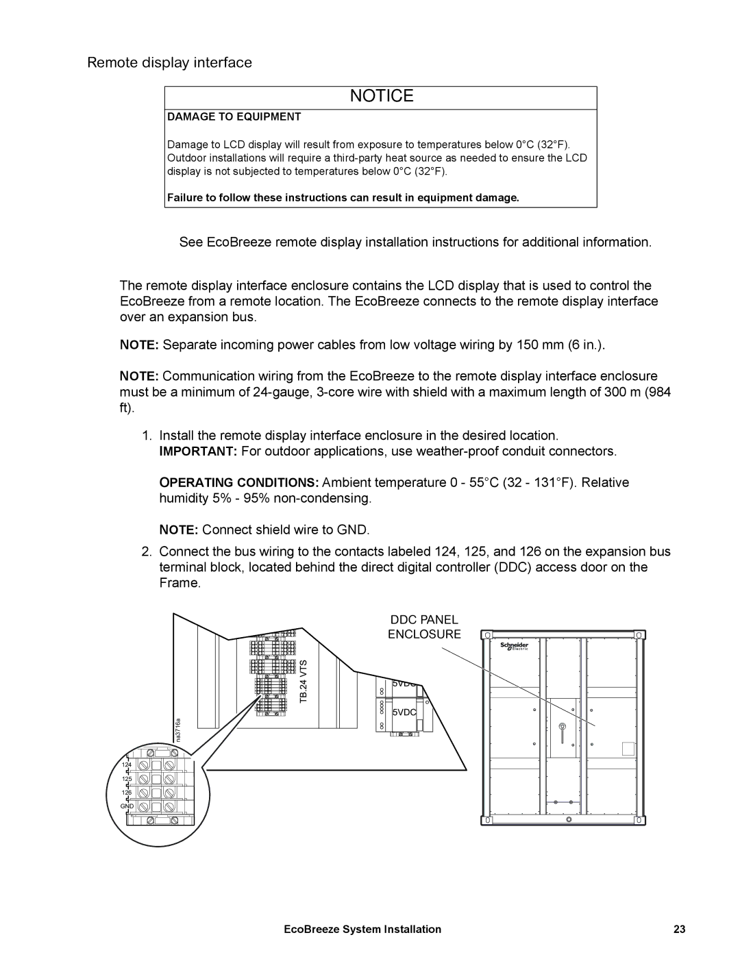
2.Connect the bus wiring to the contacts labeled 124, 125, and 126 on the expansion bus terminal block, located behind the direct digital controller (DDC) access door on the Frame.
DDC PANEL |
ENCLOSURE |
na3716a |
124 |
125 |
126 |
GND |
EcoBreeze System Installation | 23 |