ION7550, ION7650 specifications
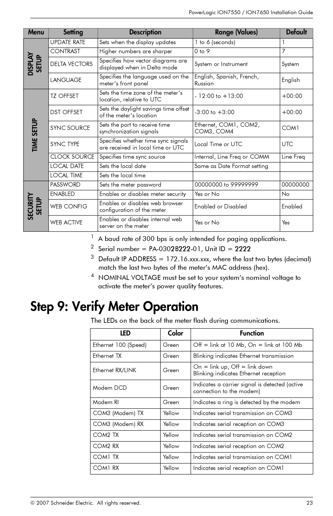
Schneider Electric has long been a leader in energy management and automation solutions, and its ION7650 and ION7550 power quality analyzers represent the pinnacle of their technology in electrical measurement. Both devices are designed to help businesses optimize energy usage, improve power quality, and enhance operational efficiency.The ION7650 is a high-performance, multi-function power quality analyzer that supports advanced applications for medium to high voltage systems. With its extensive communication capabilities and customizable configuration, it meets the needs of the most demanding power quality monitoring projects. It is equipped with a 7-inch color touchscreen interface, making it user-friendly and intuitive for operators. The ION7650 provides comprehensive analysis of power quality disturbances, such as harmonics, voltage sags, and swells, allowing for precise diagnostics of electrical issues.
On the other hand, the ION7550 focuses on providing an in-depth look at power quality for low to medium voltage systems. It shares many similarities with the ION7650 but is tailored to environments where space and installation flexibility are at a premium. With its compact design, the ION7550 can be easily integrated into existing electrical systems. Key features include real-time monitoring of voltage and current, energy consumption tracking, and the ability to log historical data for analysis.
Both the ION7650 and ION7550 are equipped with Schneider Electric's proprietary ION technology, which allows for accurate measurement of power quality metrics and energy consumption. This technology supports a wide range of protocols including Modbus, DNP3, and IEC 61850 for seamless integration into automation systems and smart grids.
One of the standout characteristics of both analyzers is their ability to provide actionable insights through advanced data visualization tools. Users can access real-time data and customizable dashboards, enabling proactive decision-making regarding energy management. Their compatibility with the EcoStruxure Platform facilitates remote monitoring and management, ensuring that energy usage is tracked and optimized across multiple sites.
In summary, the Schneider Electric ION7650 and ION7550 power quality analyzers are powerful tools designed to enhance energy management and improve operational efficiency. With their advanced technologies, user-friendly interfaces, and extensive connectivity options, they provide businesses with the insights needed to navigate the complexities of modern energy consumption and power quality issues. These devices not only promote energy savings but also support sustainability goals across various industries.

