How to Connect, Continued
Back Panel Connections
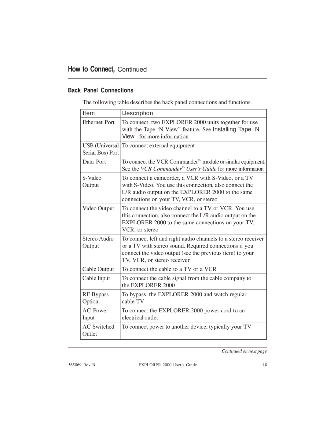
The following table describes the back panel connections and functions.
| Item | Description |
| Ethernet Port | To connect two EXPLORER 2000 units together for use |
|
| with the Tape ‘N View ™ feature. See Installing Tape ‘N |
|
| View™ for more information |
| USB (Universal | To connect external equipment |
| Serial Bus) Port |
|
|
|
|
| Data Port | To connect the VCR Commander™ module or similar equipment. |
|
| See the VCR Commander™ User’s Guide for more information |
| To connect a camcorder, a VCR with | |
| Output | with |
|
| L/R audio output on the EXPLORER 2000 to the same |
|
| connections on your TV, VCR, or stereo |
|
|
|
| Video Output | To connect the video channel to a TV or VCR. You use |
|
| this connection, also connect the L/R audio output on the |
|
| EXPLORER 2000 to the same connections on your TV, |
|
| VCR, or stereo |
|
|
|
| Stereo Audio | To connect left and right audio channels to a stereo receiver |
| Output | or a TV with stereo sound. Required connections if you |
|
| connect the video output (see the previous item) to your |
|
| TV, VCR, or stereo receiver |
| Cable Output | To connect the cable to a TV or a VCR |
|
|
|
| Cable Input | To connect the cable signal from the cable company to |
|
| the EXPLORER 2000 |
|
|
|
| RF Bypass | To bypass the EXPLORER 2000 and watch regular |
| Option | cable TV |
|
|
|
| AC Power | To connect the EXPLORER 2000 power cord to an |
| Input | electrical outlet |
|
|
|
| AC Switched | To connect power to another device, typically your TV |
| Outlet |
|
|
|
|
|
|
|
|
| Continued on next page |
565069 Rev B | EXPLORER 2000 User’s Guide | 1 8 |
