Garage Door Opener Abridor DE Puerta DE Cochera
4tI Warning
Preparing your garage door
Sectional Door One-Piece Door
Tools needed
Level Drill
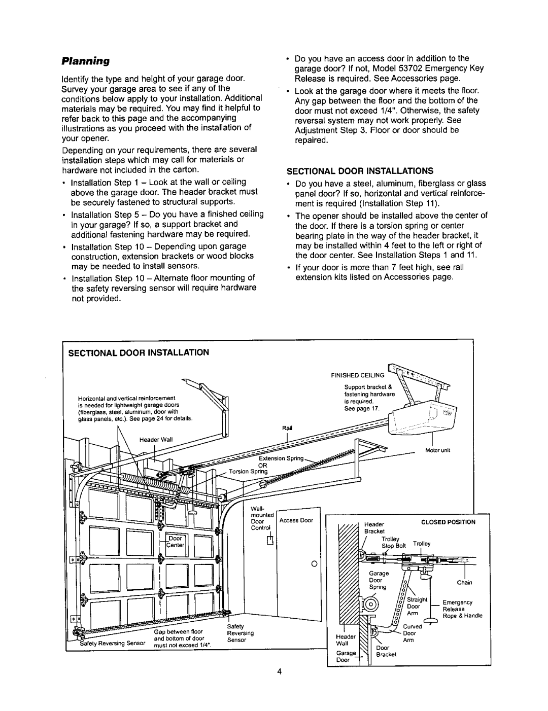
Sectional Door Installation
Sectional Door Installations
Planning
Closed Position
ONE-PIECE Door Installations
ONE-PIECE Door Without Track
ONE-PIECE Door with Track
Finished Ceiling
Carton Inventory
Installation Hardware
Assembly Hardware
Hardware Inventory
Back Rails
Assemble the Rail & Install the Trolley
To Motor Unit
Hardware Shown Actual Size
Install the Idler Pulley
On TOP and Sides Bracket
Inside Dispensin9
Master Link Cap
Sha
Sprocket
Tighten the Chain
Chain
II/2 Inch
Base fRail Mid length of Rail
Sectional Door ONE-PIECEDOOR with Track
Determine the Header Bracket Location
Proceed to ,
Example
Proceed toStep
One-piece door without track jamb hardware
One-piece door without track pivot hardware
Wall Header Bracket Installation
Ceiling Header Bracket Installation
Hole
Attach the Rail to the Header Bracket
Tempora Suppo
Position the Opener
Sectional Door or ONE-PIECE Door with Track
ONE-PIECEDOOR Without Track
Engagedreleased
StrJctural
Hardwareshownactualsize
Outside Keylock Accessory Connections
Install the Door Control
Llilllllliltltl Illliillllil
Lens Guide
Attach the Emergency Release Rope and Handle
Overhand
Reinstall the cover
Permanent Wiring Connection
Electrical Requirements
Ground Tab Green Ground Screw
Install The Safety Reversing Sensor
Important Information about Safety Reversing Sensor
Facing the door from inside the garage
Above floor
Installing the Brackets
Garage door track installation preferred
Wall installation
Floor installation
Mounting and Wiring the Safety Sensors Figure
Aligning the Safety Sensors
Troubleshooting the Safety Sensors
Opener Terminal Screws
Sectional Doors
Fasten the Door Bracket
Bracket
IIIIIIIIIIIIIIIIIIII!IIIIIII!IIIIIINut5,16HiiBo,tLkwa6r
ONE-PIECE Doors
Connect Door Arm to Trolley
Sectional Doors only
Adjustment procedures, Figure
Closed door adjustment decrease Down travel limit
Assemble the door arm, Figure
ALL ONE-PIECE Doors
Adjust the UP and Down Travel Limits
HOW and When to Adjust the Limits
Adjust the UP open force as explained in Adjustment Step
If door does not open at least 5 feet
Adjust the Force
HOW and When to Adjust the Forces
Test the Down close force
Test the UP open force
Test the Safety Reversal System
Adjust
Important Safety Check
Test the Safety Reversing Sensor
Important Safety Instructions
Using Your Garage Door Opener
Using the Wall.Mounted Door Control
Light feature
Lock feature
To Open the Door Manually
Twice a Year
Care Your Opener
Once a Year
Having a Problem?
Using the Learn Button
To Add an Additional Hand.held Remote
Control
To Erase All Codes From Motor Unit Memory
Using the Learn Button
To Add or Change a Keyless Entry PIN
Rail Assembly Parts
Installation Parts
KEY Part NO. NO.DESCRIPTION
KEY Part Description
Motor Unit Assembly Parts
Limit Switch
1817
Not Shown
Available only through Sears Parts & Service
Sears Warranty
Accesorios
Garantia
Nbmeros Servicio Contra Tapa
Introduccion
Preparaci6n de la puerta de su cochera
Puerta seccional Puerta de una sola pieza
Herramientas
Necesarias
Planificacien
Instalacion CON UNA Puerta Seccional
Fesortede torsi n
Control dl La puerta
Planificaci6n continba
Puerta DE UNA Sola Pieza SIN Carril
Instalacion CON Puertas DE UNA Sola Pieza
Puerta DE UNA Pieza CON Carril
Inventario de las cajas
53970,5393
Entrada sin Ilave
Reversa de segurdadun ojo transmisor
TORNILLERiA Y Piezas Para LA Instalacion
Inventario de piezas
TORNILLERiA Y Piezas Para EL Armado
Monte el riel e instale el trole
LA Puerta
MONTAJE, Paso
Instale la polea Ioca
Sujete el riel al motor
Estas Piezas SE Muestran /..= EN SU Tamaio Normal
Instale la cadena o cable y coloque La cubierta de la polea
Apriete la cadena
Paraercaapretarinterna
Puerta Seccional Puerta DE UNA Sola Pieza CON Carril
Determine dnde va a instalar La mnsula del cabeza
ContinUe con el Paso 2, paglna
Puerta de una pieza sin carril tornilleria del pivote
Puerta DE UNA Sola Pieza SIN Carril
Ejemplo
Sume
Instalacion DE LA M#NSULA DEL Cabezal EN LA Pared Delantera
Instale la mnsula del cabezal
Instalacion DE LA Mensula DEL Cabezal EN EL Cielo Raso
Con un
Coloque el riel en la mnsula del cabezal
Estas Piezas SE Muestran EN SU Tamaio Normal
Puerta Seccional O Puerta DE UNA Sola Peza CON Carril
Coloque el abridor
PJL Trole ixterno Trie interno
Cuelgue el abridor
INSTALACION,PASO
Fgura
No apriete en exceso
Instale la unidad de control Premium
Flgura
Instale la luce y lente
Coloque la cuerda y la manija de emergencia
INSTALACION, Paso
Requisitos para la instalaci6n elctrica
Conexioncon Cableado Permanente
Langeta
Instale el sensor del sistema de Reversa de seguridad
Vista de la puerta desde el interior de la cochera
Fstas Piezas SE Muestran EN SU Tamaio Normal
Montaje Y Cableado DE LOS Sensores DEL
Sistema DE Reversa DE Seguridad
CMO Alinear LOS Sensores DE Seguridad
Las terminales del abridor Cabe de campana
Sujete la mnsula de la puerta
Ura
Puertas Seccionales
Si su puerta es de metal, aluminio
Cielo raso
Puertas DE UNA Sola Pieza
De pulgadaRoldana de 5/16 de pulgada
Solo Para Puertas Seccionales
Conecte el brazo de la puerta al trole
Estas Piezas SE Muestran EN SU Tamano Normal
Arme el brazo de la puerta, Figura
Procedimiento de ajuste, Figura
Conecte el brazo de la puerta al trole
Posicion Completamente Cerrada
Ajuste el Iimite del recorrido hacia
Arriba y hacia abajo
Recorrldo
COMe Y Cuando Ajustar LOS LiMITES
Ajuste la fuerza
Como Y Cuando Ajustar LA Fuerza DEL Abridor
Pruebe la fuerza del recorrido hacia abajo cerrar
Pruebe la fuerza del recorrido hacia arriba abrir
Pruebe el sensor del sistema de reversa de seguridad
AJUSTES, Paso
Pruebe el sistema de reversa de seguridad
Cno usar su abridor de puerta de cochera
Active su abridor de alguna de las siguientes maneras
Cdmo abrir la puerta manualmente
C6mo usar la unidad de control de pared
Seguro
Mantenimiento De su abridor de puerta De cochera
LA Bateriadel Controlremoto
Calendario DE Mantenimiento
Dos veces al ao
Si tiene algbn problema
El control remote tiene corto alcance
Cbmo agregar un control remoto manual adicionaJ
Como Usarel BOT3NAPRENDER Learn
Controles remotos de 3 funciones
Todos los cSdigos
Para poner o cambiar el PIN de la Entrada sin Ilaves
Pies se abra completarnente
Control remoto compacto de 3 funciones
Entrada sin Ilave de funciones mOltiples
Mdnsulas de extensi6n
Www, sears.com
LE-FOYER