
139.53975SRT1, 139.53962SRT1 specifications
The Sears 139.53962SRT1 and 139.53975SRT1 are two sophisticated garage door opener models that have gained significant attention for their innovative features and technologies. These devices represent the cutting edge of convenience and security in residential garage systems.One of the standout features of both models is the integrated MyQ technology. This allows users to control their garage doors remotely using a smartphone app, ensuring seamless access even when they are away from home. Whether you’re on vacation or simply running errands, the ability to monitor and control your garage door from anywhere adds an unmatched level of convenience and peace of mind.
Both the 139.53962SRT1 and 139.53975SRT1 come equipped with a powerful ¾ HP motor. This robust motor provides sufficient lifting power for standard-sized garage doors, ensuring efficient and reliable operation. The powerful motor is designed to handle heavy doors with ease, making it a suitable choice for a variety of residential applications.
Safety is a critical aspect of garage door systems, and these models excel in this area. They feature advanced safety sensors that detect obstructions in the door’s path. This means that if something is in the way as the garage door closes, it will automatically reverse, preventing potential accidents and injuries.
In addition to safety sensors, both models are equipped with rolling code technology. This system enhances security by changing the access code every time the remote is used, preventing unauthorized access and potential break-ins.
Another noteworthy characteristic of these garage door openers is their quiet operation. Thanks to a specially designed belt drive system, both models minimize noise during operation, making them ideal for homes with living spaces situated above the garage.
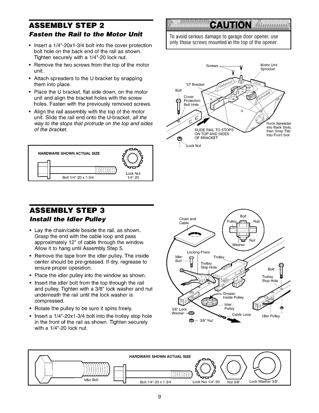
Installation is made simpler with the inclusion of detailed instructions and user-friendly components, allowing most homeowners to set up the system with minimal hassle.
Overall, the Sears 139.53962SRT1 and 139.53975SRT1 garage door openers combine powerful performance with advanced technology, safety features, and ease of use, making them top choices for anyone looking to upgrade their garage door system.