ASSEMBLY
REMOVING BLADE
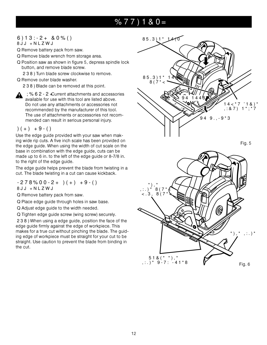
See Figure 5.
nRemove battery pack from saw.
nRemove blade wrench from storage area.
nPosition saw as shown in figure 5, depress spindle lock button, and remove blade screw.
NOTE: Turn blade screw clockwise to remove.
nRemove outer blade washer.
NOTE: Blade can be removed at this point.
WARNING: Current attachments and accessories available for use with this tool are listed above.
Do not use any attachments or accessories not recommended by the manufacturer of this tool. The use of attachments or accessories not recom- mended can result in serious personal injury.
EDGE GUIDE
Use the edge guide provided with your saw when mak- ing wide rip cuts. A five inch scale has been provided on the edge guide. When using the width of cut scale on the base in combination with the edge guide, cuts can be made up to 6 in. to the left of the edge guide or
The edge guide helps prevent the blade from twisting in a cut. The blade twisting in a cut can cause kickback.
INSTALLING EDGE GUIDE
See Figure 6.
nRemove battery pack from saw.
nPlace edge guide through holes in saw base.
nAdjust edge guide to the width needed.
nTighten edge guide screw (wing screw) securely.
NOTE: When using a edge guide, position the face of the edge guide firmly against the edge of workpiece. This makes for a true cut without pinching the blade. The guid- ing edge of workpiece must be straight for your cut to be straight. Use caution to prevent the blade from binding in the cut.
SPINDLE LOCK
SPINDLE LOCK
SCREW
| 5 |
|
|
| 40 |
|
|
| 5 |
|
|
| 3 |
|
|
| 20 |
|
|
| 2 |
|
|
3 | TO LOOSEN | LOWER BLADE | |
| 2 |
| |
| 1 | 0 | GUARD LEVER |
|
| 54 |
|
|
| TO TIGHTEN |
|
Fig. 5
EDGE
GUIDE SCREW (WING SCREW)
5 |
|
40 |
|
5 |
|
3 |
|
0 |
|
2 |
|
2 |
|
5 | EDGE GUIDE |
3 | |
4 |
|
| 2 |
| 1 |
| 0 |
PLACE EDGE |
|
GUIDE THRU HOLES | Fig. 6 |
|
12