SETTING THE BEVEL LOCK LEVER
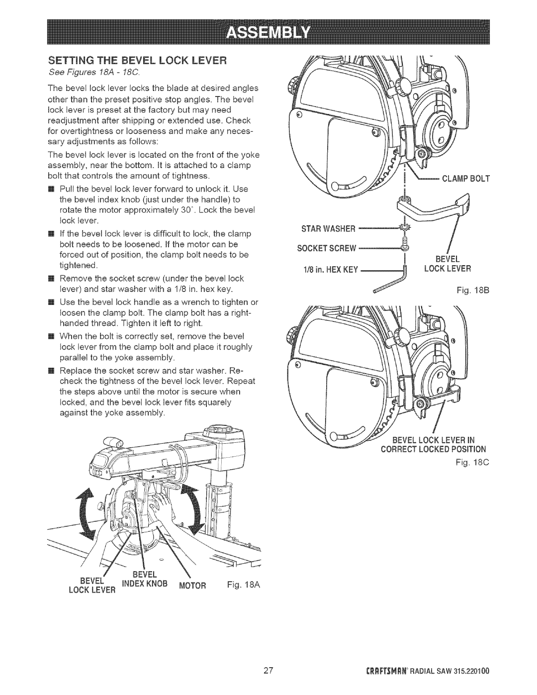
See Figures 18A- 18C.
The bevel lock lever locks the blade at desired angles |
|
|
| |
other than the preset positive stop angles. The bevel |
|
|
| |
lock lever is preset at the factory but may need |
|
|
| |
readjustment after shipping or extended use. Check |
|
|
| |
for overtightness or looseness and make any neces- |
|
|
| |
sary adjustments | as follows: |
|
|
|
The bevel lock lever is located on the front of the yoke |
|
|
| |
assembly, near the bottom. It is attached to a clamp |
|
|
| |
bolt that controls | the amount of tightness. |
| CLAMPBOLT | |
[] Pull the bevel lock lever forward to unlock it. Use | m |
|
| |
|
|
| ||
the bevel index knob (just under the handle) to |
|
|
| |
rotate the motor approximately 30 °. Lock the bevel |
|
|
| |
lock lever. |
|
|
|
|
[] if the bevel lock lever is difficult to lock, the clamp |
|
|
| |
bolt needs to be loosened. If the motor can be |
|
|
| |
forced out of position, the clamp bolt needs to be | I | BEVEL |
| |
tightened. |
|
| ||
1/8 in. BEXKEY | ./_ | LOCKLEVER |
| |
|
| |||
[] Remove the socket screw (under the bevel lock |
|
|
| |
lever) and star washer with a 1/8 in. hex key. |
| Fig. | 18B | |
[] Use the bevel lock handle as a wrench to tighten or |
|
|
| |
loosen the clamp bolt. The clamp bolt has a right- |
|
|
| |
handed thread. Tighten it left to right. |
|
|
| |
[] When the bolt is correctly set, remove the bevel |
|
|
| |
lock lever from the clamp bolt and place it roughly |
|
|
| |
parallel to the yoke assembly. |
|
|
| |
[] Replace the socket screw and star washer. Re- |
|
|
| |
check the tightness of the bevel lock lever. Repeat |
|
|
| |
the steps above until the motor is secure when |
|
|
| |
locked, and the bevel lock lever fits squarely |
|
|
| |
against the yoke assembly. |
|
|
| |
|
|
| / |
|
|
| BEVELLOCK LEVERiN | ||
|
| CORRECTLOCKEDPOSITION | ||
|
|
| Fig. | 18C |
BEVEL
BEVEL INDEXKNOB MOTOR Fig. 18A
LOCK LEVER
27 | t:RRFTSMnN RADIAL SAW 315.220100 |