FEATURES LiST
See Figures 9A - 9D.
ADJUSTABLE TABLES - A narrow spacer table and wider rear table that can be repositioned or even replaced with different tables. See Figure 9C.
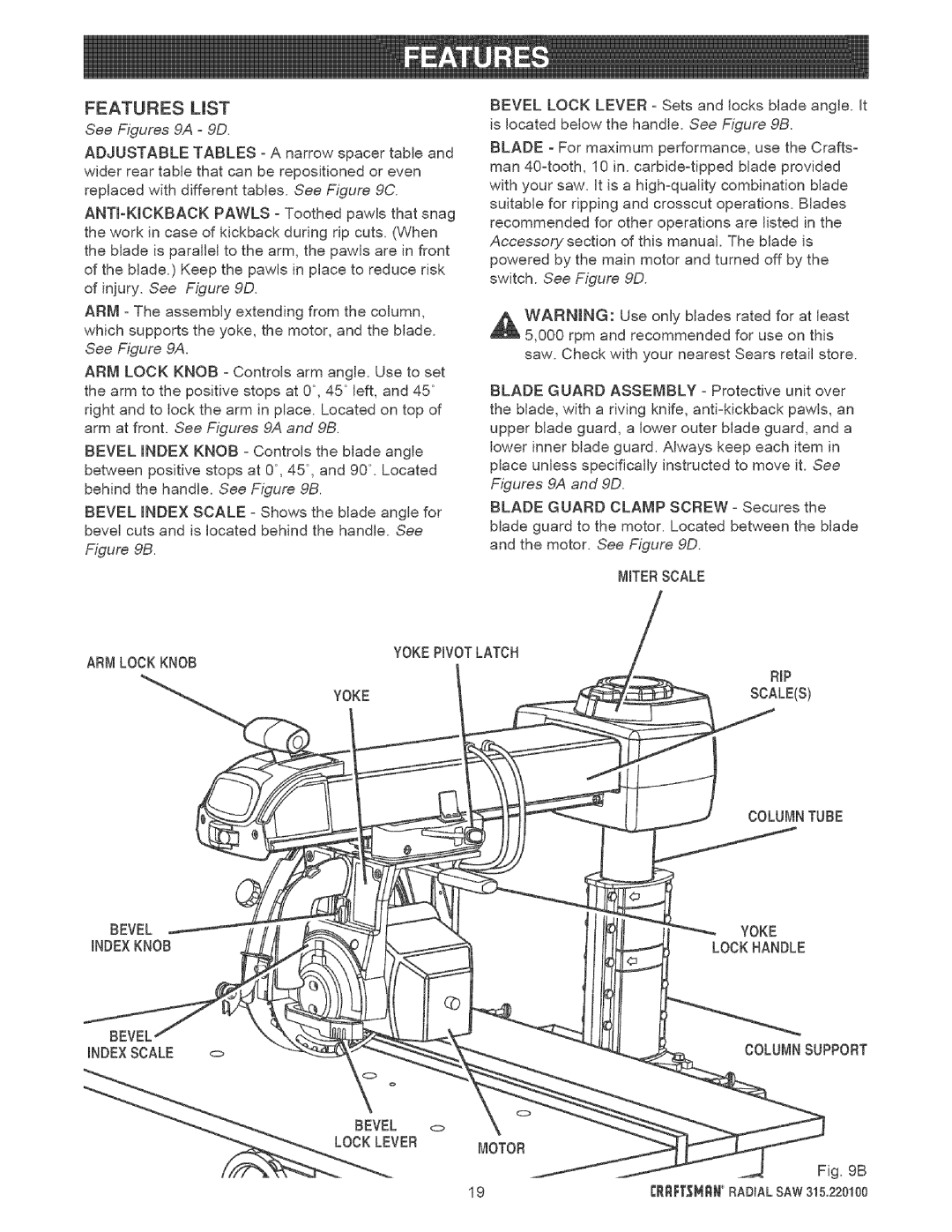
ARM - The assembly extending from the column, which supports the yoke, the motor, and the blade. See Figure 9A.
ARM LOCK KNOB - Controls arm angle. Use to set the arm to the positive stops at 0°, 45 ° left, and 45 ° right and to lock the arm in place. Located on top of arm at front. See Figures 9A and 9B.
BEVEL INDEX KNOB - Controls the blade angle between positive stops at 0°, 45 °, and 90 °. Located behind the handle. See Figure 9B.
BEVEL INDEX SCALE - Shows the blade angle for bevel cuts and is located behind the handle. See
Figure 9B.
BEVEL LOCK LEVER - Sets and locks blade angle, it is located below the handle. See Figure 9B.
BLADE - For maximum performance, use the Crafts- man
WARNmNG: Use only blades rated for at least 5,000 rpm and recommended for use on this saw. Check with your nearest Sears retail store.
BLADE GUARD ASSEMBLY - Protective unit over the blade, with a riving knife,
BLADE GUARD CLAMP SCREW - Secures the blade guard to the motor. Located between the blade and the motor. See Figure 9D.
MITERSCALE
ARM LOCK KNOB | YOKEPIVOTLATCH | |
RIP | ||
| ||
YOKE | SCALE{S) |
COLUMNTUBE
BEVEL
INDEXKNOB
BEVEL
INDEXSCALE o
i
\ ° | o |
YOKE
LOCKHANDLE
COLUMNSUPPORT
BEVEL <>
__:__V | ER | MOTOR |
19