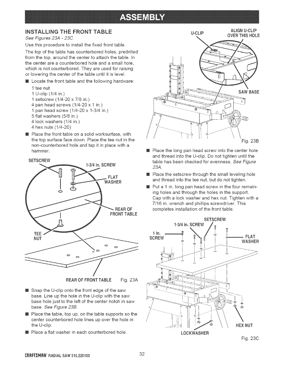
iNSTALLiNG | THE | FRONT TABLE |
|
|
|
| |||||
See Figures 23A - 23C. |
|
|
|
| OVERTHiSHOLE | ||||||
|
|
|
|
|
|
|
| ||||
Use this procedure to install the fixed front table. |
|
|
|
|
|
|
| ||||
The top of the table has counterbored holes, predrifled |
|
|
|
|
|
|
| ||||
from the top, around the center to attach the table, in |
|
|
|
|
|
|
| ||||
the center are a counterbored hole and a small hole, |
|
|
|
|
|
|
| ||||
which is not counterbored. They are used for raising |
|
|
|
|
|
|
| ||||
or lowering the center of the table until it is level. |
|
|
|
|
|
|
| ||||
[] Locate the front table and the following hardware: |
|
|
|
|
|
|
| ||||
1 tee nut |
|
|
|
|
|
|
|
|
| SAW BASE | |
1 |
|
|
|
|
|
|
|
| |||
|
|
|
|
|
|
|
|
| |||
1 setscrew | x 7/8 in.) |
|
|
|
|
|
|
| |||
4 pan | head | screws | x 1 in.) |
|
|
|
|
|
|
| |
1 pan | head | screw | x |
|
|
|
|
|
|
| |
5 flat washers (5/8 in.) |
|
|
|
|
|
|
|
| |||
4 lock washers (1/4 in.) |
|
|
|
|
|
|
|
| |||
4 hex nuts |
|
|
|
|
|
|
|
|
| ||
[] Place the front table on a solid worksurface, with |
|
|
|
|
|
|
| ||||
the top surface face down. Place the tee nut in the |
|
|
|
|
|
| Fig. 23B | ||||
|
|
|
|
|
| ||||||
|
|
|
|
|
|
| |||||
hammer. |
|
| [] | Place the | long pan | head | screw into the center hole | ||||
SETSCREW |
|
|
| and thread into the | |||||||
|
|
| table has been checked for evenness. See Figure | ||||||||
|
|
|
|
| |||||||
_ |
|
|
| SCREW | 23A. |
|
|
|
|
|
|
|
|
|
|
|
|
|
|
|
| ||
|
|
|
| [] Place the setscrew through the small leveling hole | |||||||
|
|
|
|
| and thread into the tee nut, but do not tighten. | ||||||
|
|
|
| [] Put a 1 in. long pan head screw in the four remain- | |||||||
|
|
|
|
| ing holes and through the holes in the support. | ||||||
|
|
|
|
| Cap with a lock washer and hex nut. Tighten with a | ||||||
|
|
|
|
| 7/16 in. wrench and phillips screwdriver. This | ||||||
|
| _ |
| / _'_ REAROF | completes | installation of the front | table. | ||||
|
|
|
|
|
|
|
|
| SETSCREW |
| |
|
|
|
|
|
|
|
|
| |||
|
|
|
|
| 1 in. | _ |
|
| , | !, | FLAT |
|
|
|
|
| SCREW | Z | Z | ! |
| WASHER | |
|
|
|
|
|
|
|
| ||||
REAROF FRONTTABLE | Fig. 23A |
|
[] Snap the |
| |
base. Line up the hole in the |
| |
base hole just to the left of the center notch in saw |
| |
base. See Figure 23B. |
|
|
[] Place the table, top up, on the table supports so the |
| |
center counterbored hole lines up over the hole in |
| |
the |
| HEX NUT |
[] Place a fiat washer in each counterbored | hole. | LOCKWASNER |
Fig. 23C
CRRF[_NRN RADIAL SAW 315.220100 | 32 |