I GUIDES TO
_) SOLUTION INJECTION BETWEEN THE
1. Turn off the electrical power to the well pump
and turn off the gas or electric supply to the water heater,
2.Open a faucet for a few seconds to bleed off water pressure, then close
3o Close the
NOTE: If you have a
4.Open the drain valve on the well pump, if it has one
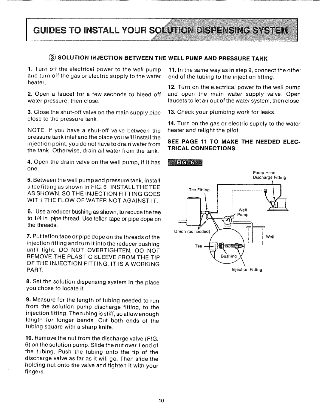
5.Between the well pump and pressure tank, install
ateefittingasshown in FIG 6 INSTALLTHETEE
AS SHOWN, SO THE INJECTION FITTING GOES WITH THE FLOW OF WATER NOT AGAINST IT
6.Use a reducer bushing as shown, to reduce the tee
to 1/4 in_ pipe thread. Use teflon tape or pipe dope on the threads
7.Put teflon tape or pipe dope on the threads of the
injection fitting and turn it into the reducer bushing
until tight. DO NOT OVERTIGHTEN DO NOT REMOVE THE PLASTIC SLEEVE FROM THE TIP
OF THE INJECTION FITTING IT IS A WORKING PART.
8.Set the solution dispensing system in the place you chose to locate it
WELL PUMP AND PRESSURE TANK
11.In the same way as in step 9, connect the other end of the tubing to the injection fitting.
12.Turn on the electrical power to the well pump and open the main water supply valve. Oper faucets to let air out of the water system, then close
13.Check your plumbing work for leaks.
14.Turn on the gas or electric supply to the water heater and relight the pilot.
SEE PAGE 11 TO MAKE THE NEEDED ELEC- TRICAL CONNECTIONS.
| Pump Head | |
| Discharge | Fitting |
TeoF,.,o0I | I | / |
Injection Fitting
9.Measure for the length of tubing needed to run from the solution pump discharge fitting, to the
injection fitting. The tubing is stiff, so allow enough length for longer bends. Cut both ends of the
tubing square with a sharp knife.
10.Remove the nut from the discharge valve (FIG.
6)on the solution pump. Slide the nut over lendof the tubing. Push the tubing onto the tip of the discharge valve as far as it will go_ Then slide the holding nut onto the valve and tighten it with your fingers.
10