OPERATION
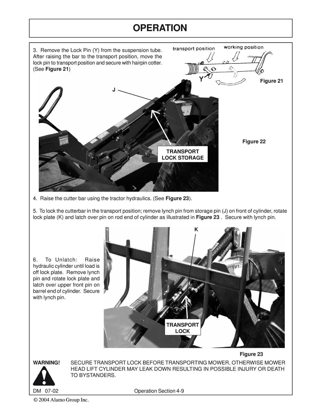
3.Remove the Lock Pin (Y) from the suspension tube. After raising the bar to the transport position, move the lock pin to transport position and secure with hairpin cotter. (See Figure 21)
Figure 21
J
Figure 22
TRANSPORT
LOCK STORAGE
4.Raise the cutter bar using the tractor hydraulics. (See Figure 23).
5.To lock the cutterbar in the transport position; remove lynch pin from storage pin (J) on front of cylinder, rotate lock plate (K) and latch over pin on rod end of cylinder as illustrated in Figure 23 . Secure with lynch pin.
K
6.To Unlatch: Raise hydraulic cylinder until load is off lock plate. Remove lynch pin and rotate lock plate and latch over upper front pin on barrel end of cylinder. Secure with lynch pin.
TRANSPORT
LOCK
Figure 23
WARNING! SECURE TRANSPORT LOCK BEFORE TRANSPORTING MOWER, OTHERWISE MOWER HEAD LIFT CYLINDER MAY LEAK DOWN RESULTING IN POSSIBLE INJURY OR DEATH TO BYSTANDERS.
DM | Operation Section |