OPERATION
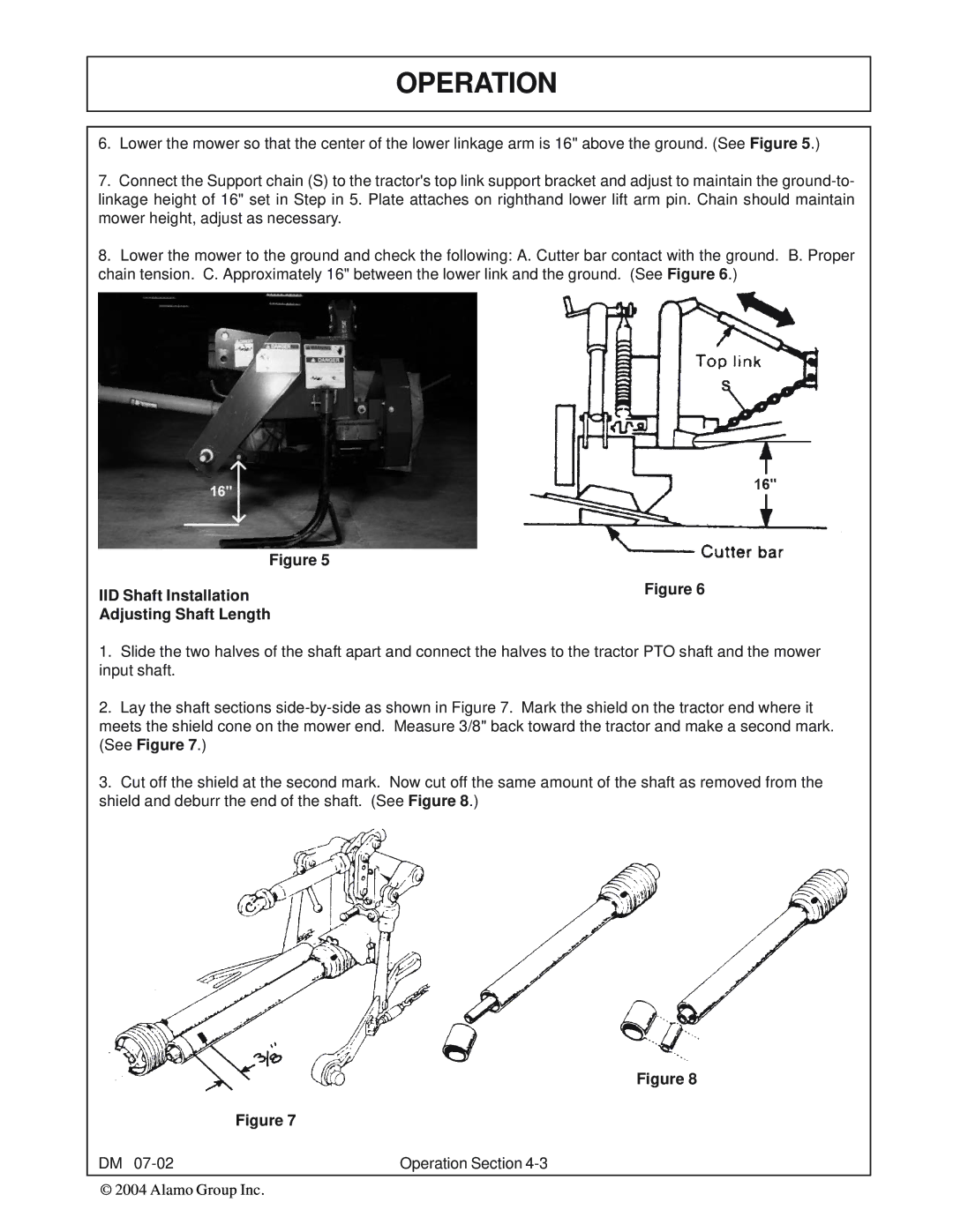
6.Lower the mower so that the center of the lower linkage arm is 16" above the ground. (See Figure 5.)
7.Connect the Support chain (S) to the tractor's top link support bracket and adjust to maintain the
8.Lower the mower to the ground and check the following: A. Cutter bar contact with the ground. B. Proper chain tension. C. Approximately 16" between the lower link and the ground. (See Figure 6.)
Figure 5 |
|
IID Shaft Installation | Figure 6 |
Adjusting Shaft Length |
|
1.Slide the two halves of the shaft apart and connect the halves to the tractor PTO shaft and the mower input shaft.
2.Lay the shaft sections
meets the shield cone on the mower end. Measure 3/8" back toward the tractor and make a second mark. (See Figure 7.)
3.Cut off the shield at the second mark. Now cut off the same amount of the shaft as removed from the shield and deburr the end of the shaft. (See Figure 8.)
Figure 8
Figure 7
DM | Operation Section |