R-22AT

R-24AT

5.Remove the power supply cord.

Re-install

1.Insert the power supply cord into the cord bushing.

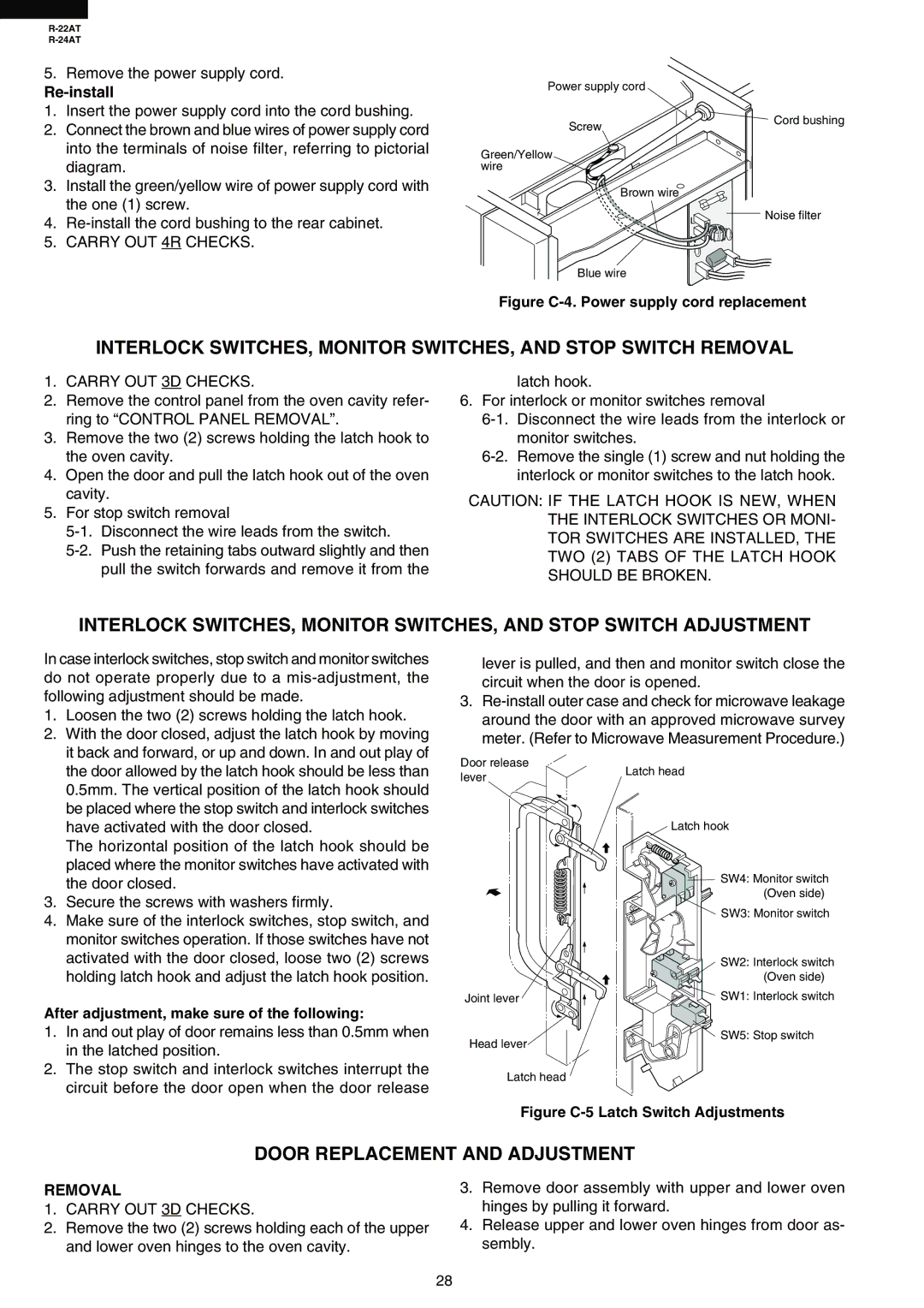
2.Connect the brown and blue wires of power supply cord into the terminals of noise filter, referring to pictorial diagram.

3.Install the green/yellow wire of power supply cord with the one (1) screw.

4.Re-install the cord bushing to the rear cabinet.

5.CARRY OUT 4R CHECKS.

Power supply cord

Screw

Green/Yellow wire

Brown wire

Blue wire

Cord bushing

LNoise filter

N

Figure C-4. Power supply cord replacement

INTERLOCK SWITCHES, MONITOR SWITCHES, AND STOP SWITCH REMOVAL

1.CARRY OUT 3D CHECKS.

2.Remove the control panel from the oven cavity refer- ring to “CONTROL PANEL REMOVAL”.

3.Remove the two (2) screws holding the latch hook to the oven cavity.

4.Open the door and pull the latch hook out of the oven cavity.

5.For stop switch removal

5-1. Disconnect the wire leads from the switch.

5-2. Push the retaining tabs outward slightly and then pull the switch forwards and remove it from the

latch hook.

6.For interlock or monitor switches removal

6-1. Disconnect the wire leads from the interlock or monitor switches.

6-2. Remove the single (1) screw and nut holding the interlock or monitor switches to the latch hook.

CAUTION: IF THE LATCH HOOK IS NEW, WHEN THE INTERLOCK SWITCHES OR MONI- TOR SWITCHES ARE INSTALLED, THE TWO (2) TABS OF THE LATCH HOOK SHOULD BE BROKEN.

INTERLOCK SWITCHES, MONITOR SWITCHES, AND STOP SWITCH ADJUSTMENT

In case interlock switches, stop switch and monitor switches do not operate properly due to a mis-adjustment, the following adjustment should be made.

1.

Loosen the two (2) screws holding the latch hook.

2.

With the door closed, adjust the latch hook by moving


it back and forward, or up and down. In and out play of

lever is pulled, and then and monitor switch close the circuit when the door is opened.

3.Re-install outer case and check for microwave leakage around the door with an approved microwave survey meter. (Refer to Microwave Measurement Procedure.)

the door allowed by the latch hook should be less than

0.5mm. The vertical position of the latch hook should

be placed where the stop switch and interlock switches

have activated with the door closed.

The horizontal position of the latch hook should be

placed where the monitor switches have activated with

the door closed.

3. Secure the screws with washers firmly.

4. Make sure of the interlock switches, stop switch, and

monitor switches operation. If those switches have not

activated with the door closed, loose two (2) screws

holding latch hook and adjust the latch hook position.

After adjustment, make sure of the following:

1.

In and out play of door remains less than 0.5mm when


in the latched position.

2.

The stop switch and interlock switches interrupt the

Door release lever

Joint lever

Head lever

Latch head

Latch hook

SW4: Monitor switch (Oven side)

SW3: Monitor switch

SW2: Interlock switch (Oven side)

SW1: Interlock switch

SW5: Stop switch

circuit before the door open when the door release

Latch head

Figure C-5 Latch Switch Adjustments

DOOR REPLACEMENT AND ADJUSTMENT

REMOVAL

1.CARRY OUT 3D CHECKS.

2.Remove the two (2) screws holding each of the upper and lower oven hinges to the oven cavity.

3.Remove door assembly with upper and lower oven hinges by pulling it forward.

4.Release upper and lower oven hinges from door as- sembly.

28

Page 30
Image 30
Sharp R-24AT, R-22AT service manual Door Replacement and Adjustment, After adjustment, make sure of the following, Removal

R-22AT, R-24AT specifications

The Sharp R-24AT and R-22AT microwave ovens are advanced kitchen appliances designed to enhance cooking convenience, efficiency, and versatility. Both models incorporate innovative technologies and features that cater to modern cooking needs.

The Sharp R-24AT boasts a robust 900 watts of cooking power, enabling users to prepare a wide variety of meals quickly and effectively. Its spacious 24-liter capacity is suitable for families and those who enjoy entertaining. One of the standout features of the R-24AT is its intelligent sensor technology, which automatically detects humidity levels in the cooking food. This innovative feature ensures optimal cooking times and temperatures, resulting in perfectly cooked dishes without the guesswork.

Another key technology in the R-24AT is the inverter cooking system. This system provides a seamless flow of power throughout the cooking process, allowing for more precise temperature control. Unlike traditional microwaves that operate in full power or off, inverter technology ensures consistent heat, which is particularly beneficial for tasks such as defrosting, reheating, and simmering.

The Sharp R-22AT, while slightly more compact with a 22-liter capacity, also delivers impressive performance with 800 watts of power. It features a similar inverter cooking system that guarantees even cooking results. Both models come with multiple auto-cook presets, providing users with a selection of quick options for common dishes such as popcorn, pizza, and oatmeal. This feature streamlines meal preparation and reduces the time spent on planning meals.

In addition, the user-friendly control panel on both models includes a combination of push-button and rotary dial controls for easy navigation. The inclusion of a bright LED display further enhances usability, allowing cooks to monitor cooking times and settings easily.

Safety is another critical aspect of the Sharp R-24AT and R-22AT. Both models come equipped with a child lock feature, ensuring peace of mind in homes with young children. The stainless steel interiors of these microwaves facilitate easy cleaning, while their sleek design adds a modern touch to any kitchen.

In summary, the Sharp R-24AT and R-22AT microwave ovens stand out for their advanced cooking technologies, user-friendly features, and thoughtful design. They empower home cooks to prepare meals with precision and ease, making them a valuable addition to any kitchen.