Sharp R-24AT Operation Sequence, Idle Condition, Microwave Cooking Condition, Figure O-1 on page

Models: R-22AT R-24AT

1 44
Download 44 pages 40.07 Kb
Page 6
Image 6
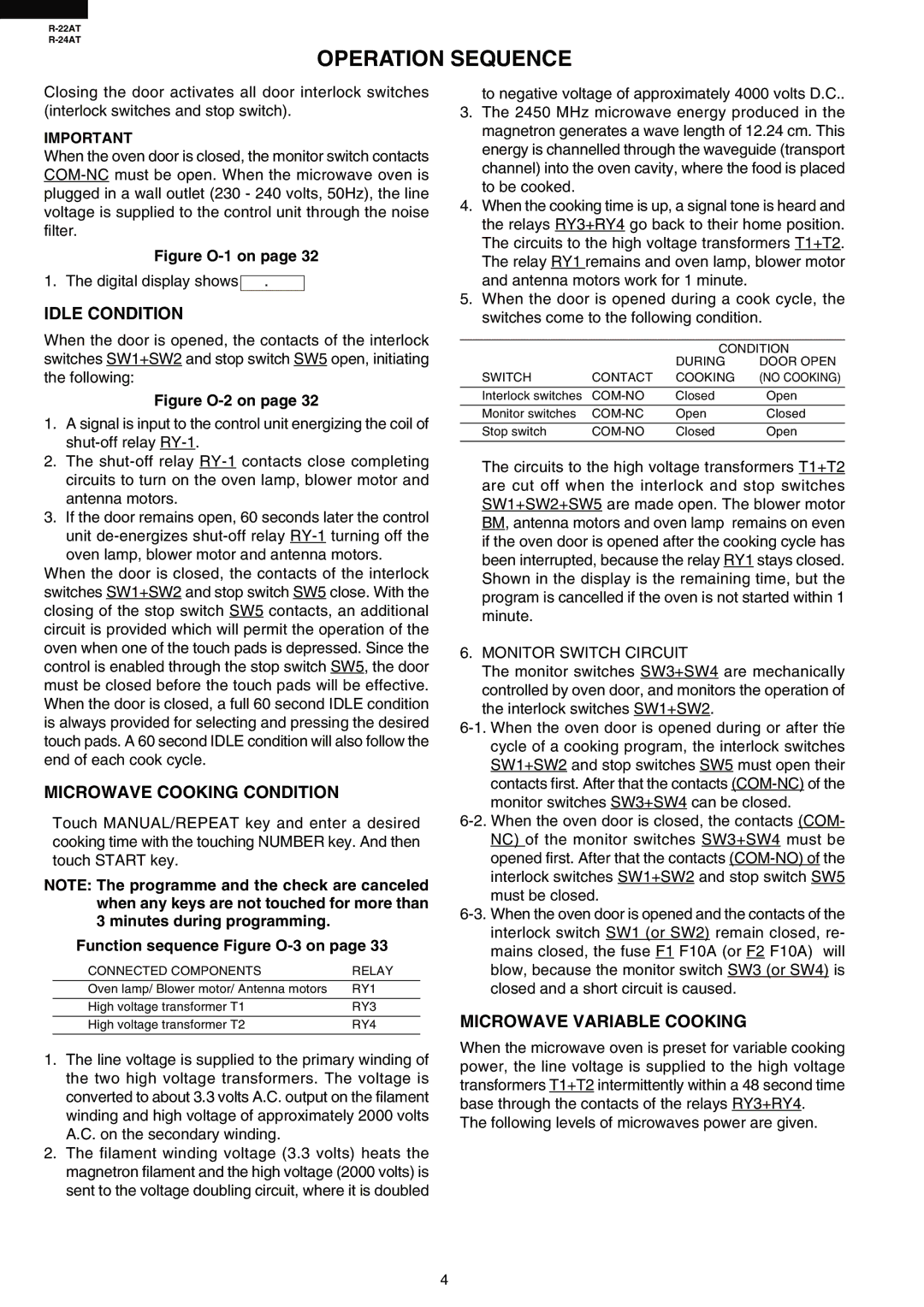
OPERATION SEQUENCE

R-22AT

R-24AT

OPERATION SEQUENCE

Closing the door activates all door interlock switches (interlock switches and stop switch).

IMPORTANT

When the oven door is closed, the monitor switch contacts COM-NC must be open. When the microwave oven is plugged in a wall outlet (230 - 240 volts, 50Hz), the line voltage is supplied to the control unit through the noise filter.

Figure O-1 on page 32

1. The digital display shows .

IDLE CONDITION

When the door is opened, the contacts of the interlock switches SW1+SW2 and stop switch SW5 open, initiating the following:

Figure O-2 on page 32

1.A signal is input to the control unit energizing the coil of shut-off relay RY-1.

2.The shut-off relay RY-1 contacts close completing circuits to turn on the oven lamp, blower motor and antenna motors.

3.If the door remains open, 60 seconds later the control unit de-energizes shut-off relay RY-1 turning off the oven lamp, blower motor and antenna motors.

When the door is closed, the contacts of the interlock switches SW1+SW2 and stop switch SW5 close. With the closing of the stop switch SW5 contacts, an additional circuit is provided which will permit the operation of the oven when one of the touch pads is depressed. Since the control is enabled through the stop switch SW5, the door must be closed before the touch pads will be effective. When the door is closed, a full 60 second IDLE condition is always provided for selecting and pressing the desired touch pads. A 60 second IDLE condition will also follow the end of each cook cycle.

MICROWAVE COOKING CONDITION

Touch MANUAL/REPEAT key and enter a desired cooking time with the touching NUMBER key. And then touch START key.

NOTE: The programme and the check are canceled when any keys are not touched for more than 3 minutes during programming.

Function sequence Figure O-3 on page 33

CONNECTED COMPONENTS

RELAY

Oven lamp/ Blower motor/ Antenna motors

RY1


High voltage transformer T1

RY3

to negative voltage of approximately 4000 volts D.C..

3.The 2450 MHz microwave energy produced in the magnetron generates a wave length of 12.24 cm. This energy is channelled through the waveguide (transport channel) into the oven cavity, where the food is placed to be cooked.

4.When the cooking time is up, a signal tone is heard and the relays RY3+RY4 go back to their home position. The circuits to the high voltage transformers T1+T2. The relay RY1 remains and oven lamp, blower motor and antenna motors work for 1 minute.

5.When the door is opened during a cook cycle, the switches come to the following condition.


CONDITION


DURING

DOOR OPEN

SWITCH

CONTACT

COOKING

(NO COOKING)


Interlock switches

COM-NO

Closed

Open


Monitor switches

COM-NC

Open

Closed


Stop switch

COM-NO

Closed

Open


The circuits to the high voltage transformers T1+T2 are cut off when the interlock and stop switches SW1+SW2+SW5 are made open. The blower motor BM, antenna motors and oven lamp remains on even if the oven door is opened after the cooking cycle has been interrupted, because the relay RY1 stays closed. Shown in the display is the remaining time, but the program is cancelled if the oven is not started within 1 minute.

6. MONITOR SWITCH CIRCUIT

The monitor switches SW3+SW4 are mechanically controlled by oven door, and monitors the operation of the interlock switches SW1+SW2.

6-1. When the oven door is opened during or after the cycle of a cooking program, the interlock switches SW1+SW2 and stop switches SW5 must open their contacts first. After that the contacts (COM-NC) of the monitor switches SW3+SW4 can be closed.

6-2. When the oven door is closed, the contacts (COM- NC) of the monitor switches SW3+SW4 must be opened first. After that the contacts (COM-NO) of the interlock switches SW1+SW2 and stop switch SW5 must be closed.

6-3. When the oven door is opened and the contacts of the interlock switch SW1 (or SW2) remain closed, re- mains closed, the fuse F1 F10A (or F2 F10A) will blow, because the monitor switch SW3 (or SW4) is closed and a short circuit is caused.

High voltage transformer T2

RY4

MICROWAVE VARIABLE COOKING

1.The line voltage is supplied to the primary winding of the two high voltage transformers. The voltage is converted to about 3.3 volts A.C. output on the filament winding and high voltage of approximately 2000 volts A.C. on the secondary winding.

2.The filament winding voltage (3.3 volts) heats the magnetron filament and the high voltage (2000 volts) is sent to the voltage doubling circuit, where it is doubled

When the microwave oven is preset for variable cooking power, the line voltage is supplied to the high voltage transformers T1+T2 intermittently within a 48 second time base through the contacts of the relays RY3+RY4.

The following levels of microwaves power are given.

4

Page 6
Image 6
Sharp R-24AT, R-22AT Operation Sequence, Idle Condition, Microwave Cooking Condition, Microwave Variable Cooking