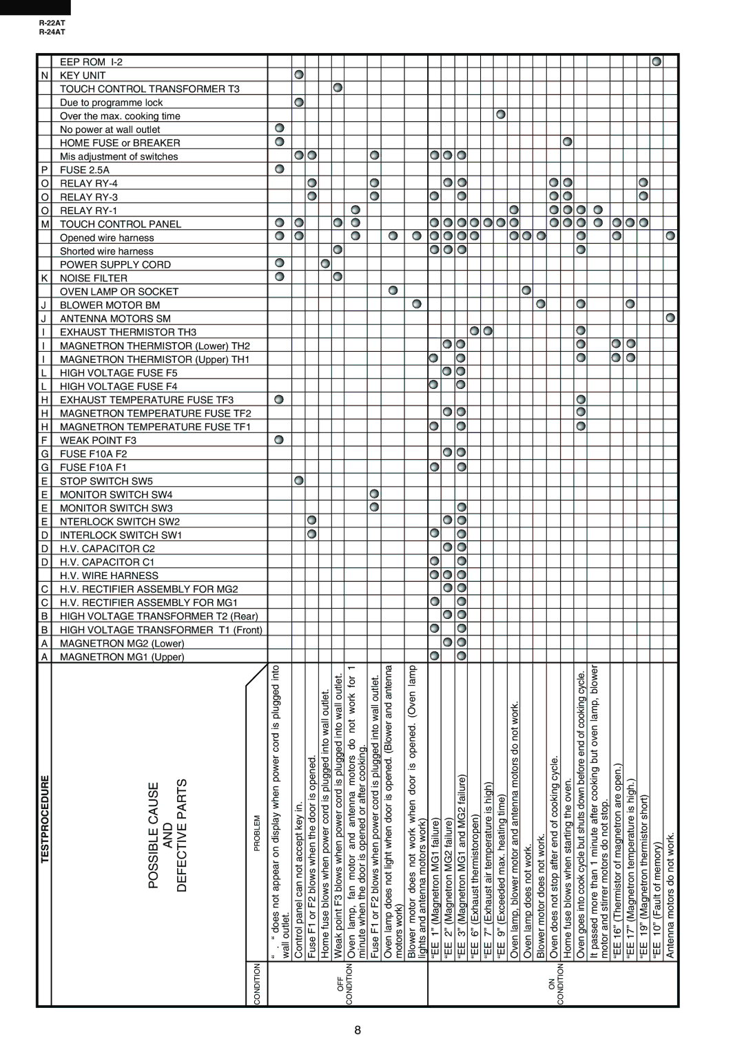
Sharp R-24AT, R-22AT service manual Possible Cause And Defective Parts, Testprocedure

Models: R-22AT R-24AT

1 44
Download 44 pages 40.07 Kb
Page 10
Image 10
TESTPROCEDURE

R-22AT

R-24AT


EEP ROM I-2


N

KEY UNIT


TOUCH CONTROL TRANSFORMER T3


Due to programme lock


Over the max. cooking time


No power at wall outlet


HOME FUSE or BREAKER


Mis adjustment of switches


P

FUSE 2.5A


O

RELAY RY-4


O

RELAY RY-3


O

RELAY RY-1


M

TOUCH CONTROL PANEL


Opened wire harness


Shorted wire harness


POWER SUPPLY CORD


K

NOISE FILTER


OVEN LAMP OR SOCKET


J

BLOWER MOTOR BM


J

ANTENNA MOTORS SM


I

EXHAUST THERMISTOR TH3


I

MAGNETRON THERMISTOR (Lower) TH2


I

MAGNETRON THERMISTOR (Upper) TH1


L

HIGH VOLTAGE FUSE F5


L

HIGH VOLTAGE FUSE F4


H

EXHAUST TEMPERATURE FUSE TF3


H

MAGNETRON TEMPERATURE FUSE TF2


H

MAGNETRON TEMPERATURE FUSE TF1


F

WEAK POINT F3


G

FUSE F10A F2


G

FUSE F10A F1


E

STOP SWITCH SW5


E

MONITOR SWITCH SW4


E

MONITOR SWITCH SW3


E

NTERLOCK SWITCH SW2


D

INTERLOCK SWITCH SW1


D

H.V. CAPACITOR C2


D

H.V. CAPACITOR C1


H.V. WIRE HARNESS


C

H.V. RECTIFIER ASSEMBLY FOR MG2


C

H.V. RECTIFIER ASSEMBLY FOR MG1


B

HIGH VOLTAGE TRANSFORMER T2 (Rear)


B

HIGH VOLTAGE TRANSFORMER T1 (Front)


A

MAGNETRON MG2 (Lower)


A

MAGNETRON MG1 (Upper)


TESTPROCEDURE

POSSIBLE CAUSE AND DEFECTIVE PARTS

PROBLEM

“ . “ does not appear on display when power cord is plugged into wall outlet.

Control panel can not accept key in.

Fuse F1 or F2 blows when the door is opened.

Home fuse blows when power cord is plugged into wall outlet.

Weak point F3 blows when power cord is plugged into wall outlet.

Oven lamp, fan motor and antenna motors do not work for 1 minute when the door is opened or after cooking.

Fuse F1 or F2 blows when power cord is plugged into wall outlet.

Oven lamp does not light when door is opened. (Blower and antenna motors work)

Blower motor does not work when door is opened. (Oven lamp lights and antenna motors work)

“EE 1” (Magnetron MG1 failure)

“EE 2” (Magnetron MG2 failure)

“EE 3” (Magnetron MG1 and MG2 failure)

“EE 6” (Exhaust thermistoropen)

“EE 7” (Exhaust air temperature is high)

“EE 9” (Exceeded max. heating time)

Oven lamp, blower motor and antenna motors do not work.

Oven lamp does not work.

Blower motor does not work.

Oven does not stop after end of cooking cycle.


Home fuse blows when starting the oven.

Oven goes into cook cycle but shuts down before end of cooking cycle.

It passed more than 1 minute after cooking but oven lamp, blower motor and stirrer motors do not stop.

“EE 16” (Thermistor of magnetron are open.)

“EE 17” (Magnetron temperature is high.)

“EE 19” (Magnetron thermistor short)

“EE 10” (Fault of memory)

Antenna motors do not work.


CONDITION


OFF CONDITION


ON

CONDITION

8

Page 10
Image 10
Sharp R-24AT, R-22AT service manual Possible Cause And Defective Parts, Testprocedure