R-22AT

R-24AT

Pin No.

Signal

I/O


Description


19

P47

OUT

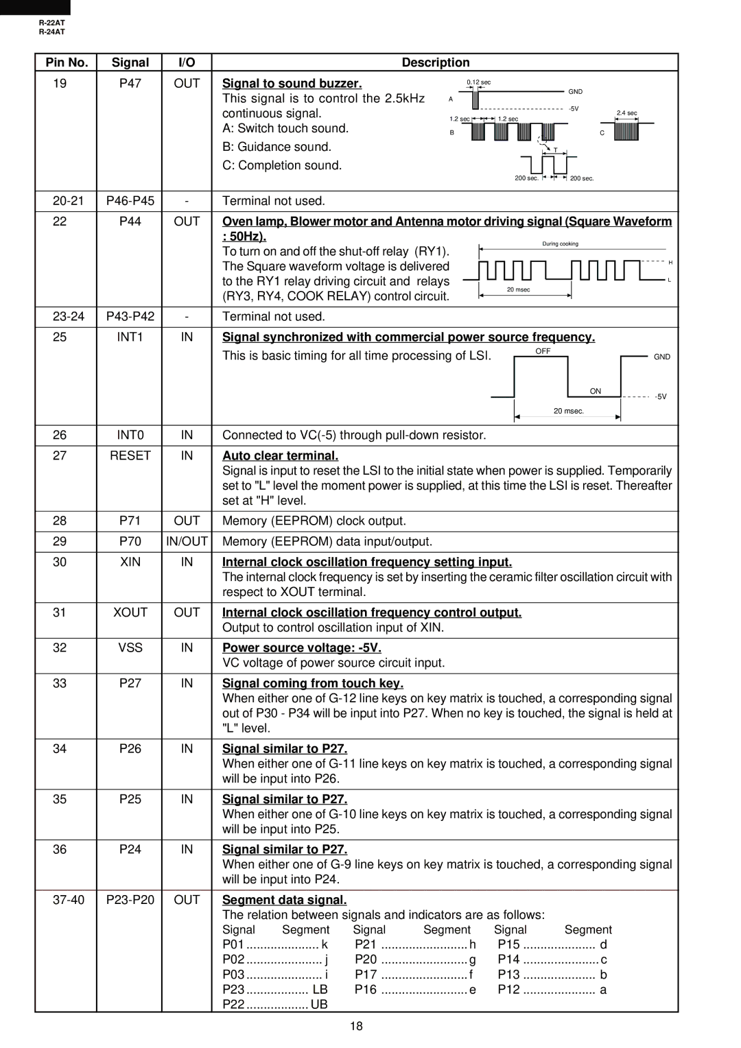
Signal to sound buzzer.


0.12 sec


This signal is to control the 2.5kHz


GND


A


-5V


continuous signal.


1.2 sec


1.2 sec


2.4 sec


A: Switch touch sound.


B


C


B: Guidance sound.


T


C: Completion sound.


200 sec.


200 sec.


20-21

P46-P45

-

Terminal not used.


22

P44

OUT

Oven lamp, Blower motor and Antenna motor driving signal (Square Waveform


: 50Hz).


During cooking


To turn on and off the shut-off relay (RY1).


The Square waveform voltage is delivered


H


to the RY1 relay driving circuit and

relays


L


(RY3, RY4, COOK RELAY) control circuit.


20 msec


23-24

P43-P42

-

Terminal not used.


25

INT1

IN

Signal synchronized with commercial power source frequency.


This is basic timing for all time processing of LSI.


OFF


GND


ON


-5V


20 msec.


26

INT0

IN

Connected to VC(-5) through pull-down resistor.


27

RESET

IN

Auto clear terminal.


Signal is input to reset the LSI to the initial state when power is supplied. Temporarily


set to "L" level the moment power is supplied, at this time the LSI is reset. Thereafter


set at "H" level.


28

P71

OUT

Memory (EEPROM) clock output.


29

P70

IN/OUT

Memory (EEPROM) data input/output.


30

XIN

IN

Internal clock oscillation frequency setting input.


The internal clock frequency is set by inserting the ceramic filter oscillation circuit with


respect to XOUT terminal.


31

XOUT

OUT

Internal clock oscillation frequency control output.


Output to control oscillation input of XIN.


32

VSS

IN

Power source voltage: -5V.


VC voltage of power source circuit input.


33

P27

IN

Signal coming from touch key.


When either one of G-12 line keys on key matrix is touched, a corresponding signal


out of P30 - P34 will be input into P27. When no key is touched, the signal is held at


"L" level.


34

P26

IN

Signal similar to P27.


When either one of G-11 line keys on key matrix is touched, a corresponding signal


will be input into P26.


35

P25

IN

Signal similar to P27.


When either one of G-10 line keys on key matrix is touched, a corresponding signal


will be input into P25.


36

P24

IN

Signal similar to P27.


When either one of G-9 line keys on key matrix is touched, a corresponding signal


will be input into P24.


37-40

P23-P20

OUT

Segment data signal.


The relation between signals and indicators are as follows:


Signal

Segment

Signal

Segment

Signal


Segment


P01

k

P21


h

P15


d


P02

j

P20


g

P14


c


P03

i

P17


f

P13


b


P23

LB

P16


e

P12


a


P22

UB


18

Page 20
Image 20
Sharp R-24AT Signal to sound buzzer, 50Hz, Signal synchronized with commercial power source frequency, Auto clear terminal

R-22AT, R-24AT specifications

The Sharp R-24AT and R-22AT microwave ovens are advanced kitchen appliances designed to enhance cooking convenience, efficiency, and versatility. Both models incorporate innovative technologies and features that cater to modern cooking needs.

The Sharp R-24AT boasts a robust 900 watts of cooking power, enabling users to prepare a wide variety of meals quickly and effectively. Its spacious 24-liter capacity is suitable for families and those who enjoy entertaining. One of the standout features of the R-24AT is its intelligent sensor technology, which automatically detects humidity levels in the cooking food. This innovative feature ensures optimal cooking times and temperatures, resulting in perfectly cooked dishes without the guesswork.

Another key technology in the R-24AT is the inverter cooking system. This system provides a seamless flow of power throughout the cooking process, allowing for more precise temperature control. Unlike traditional microwaves that operate in full power or off, inverter technology ensures consistent heat, which is particularly beneficial for tasks such as defrosting, reheating, and simmering.

The Sharp R-22AT, while slightly more compact with a 22-liter capacity, also delivers impressive performance with 800 watts of power. It features a similar inverter cooking system that guarantees even cooking results. Both models come with multiple auto-cook presets, providing users with a selection of quick options for common dishes such as popcorn, pizza, and oatmeal. This feature streamlines meal preparation and reduces the time spent on planning meals.

In addition, the user-friendly control panel on both models includes a combination of push-button and rotary dial controls for easy navigation. The inclusion of a bright LED display further enhances usability, allowing cooks to monitor cooking times and settings easily.

Safety is another critical aspect of the Sharp R-24AT and R-22AT. Both models come equipped with a child lock feature, ensuring peace of mind in homes with young children. The stainless steel interiors of these microwaves facilitate easy cleaning, while their sleek design adds a modern touch to any kitchen.

In summary, the Sharp R-24AT and R-22AT microwave ovens stand out for their advanced cooking technologies, user-friendly features, and thoughtful design. They empower home cooks to prepare meals with precision and ease, making them a valuable addition to any kitchen.