ENGLISH |
| ENGLISH |
|
1
A B
2
3 | 4 | 5 | 6 | 7 | 8 | 9 | 10 | 11 |
12
13 | 14 | 15 | 16 | 17 | 17 |
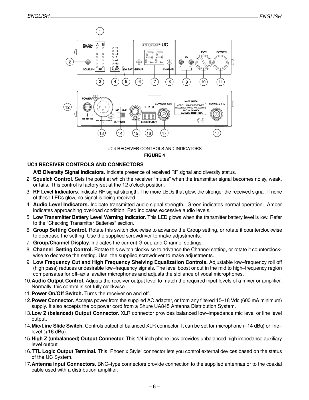
UC4 RECEIVER CONTROLS AND INDICATORS
FIGURE 4
UC4 RECEIVER CONTROLS AND CONNECTORS
1.A/B Diversity Signal Indicators. Indicate presence of received RF signal and diversity status.
2.Squelch Control. Sets the point at which the receiver ªmutesº when the transmitter signal becomes noisy, weak, or fails. This control is
3.RF Level Indicators. Indicate RF signal strength. The more LEDs that glow, the stronger the received signal. If none of these LEDs glow, no signal is being received.
4.Audio Level Indicators. Indicate transmitted audio signal strength. Green indicates normal operation. Amber indicates approaching overload condition. Red indicates excessive audio levels.
5.Low Transmitter Battery Level Warning Indicator. This LED glows when the transmitter battery level is low. Refer to the ªChecking Transmitter Batteriesº section.
6.Group Setting Control. Rotate this switch clockwise to advance the Group setting, or rotate it counterclockwise to decrease the setting. Use the supplied screwdriver to make adjustments.
7.Group/Channel Display. Indicates the current Group and Channel settings.
8.Channel Setting Control. Rotate this switch clockwise to advance the Channel setting, or rotate it counterclock- wise to decrease the setting. Use the supplied screwdriver to make adjustments.
9.Low Frequency Cut and High Frequency Shelving Equalization Controls. Adjustable low±frequency roll off (high pass) reduces undesirable low±frequency signals. The level boost or cut in the mid to high±frequency region compensates for off±axis lavalier microphones and adjusts the sibilance of vocal microphones.
10.Audio Output Control. Adjusts the receiver output level to match the required input levels of a mixer or amplifier. Normally, this control is set fully clockwise.
11. Power On/Off Switch. Turns the receiver on and off.
12.Power Connector. Accepts power from the supplied AC adapter, or from any filtered 15±18 Vdc (600 mA minimum) supply. It also accepts the dc power cord from a Shure UA845 Antenna Distribution System.
13.Low Z (balanced) Output Connector. XLR connector provides balanced low±impedance mic level or line level output.
14.Mic/Line Slide Switch. Controls output of balanced XLR connector. It can be set for microphone (±14 dBu) or line± level (+16 dBu).
15.High Z (unbalanced) Output Connector. This 1/4 inch phone jack provides unbalanced high impedance auxiliary level output.
16.TTL Logic Output Terminal. This ªPhoenix Styleº connector lets you control external devices based on the status of the UC System.
17.Antenna Input Connectors. BNC±type connectors provide connection to the supplied antennas or to the coaxial cable used with a distribution amplifier.
± 6 ±
