www.supportme.net
3.3 Connector locations
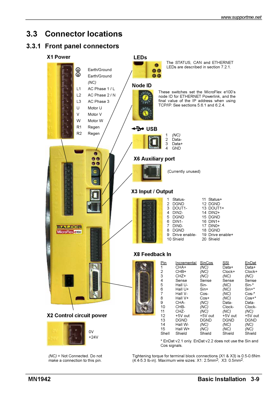
3.3.1 Front panel connectors
X1 Power
Earth/Ground
Earth/Ground
(NC)
L1 AC Phase 1 / L
L2 AC Phase 2 / N
L3 AC Phase 3
U Motor U
V Motor V
W Motor W
R1 Regen
R2 Regen
X2 Control circuit power
0V
+24V
(NC) = Not Connected. Do not make a connection to this pin.
LEDs
The STATUS, CAN and ETHERNET
LEDs are described in section 7.2.1.
Node ID
These switches set the MicroFlex e100’s node ID for ETHERNET Powerlink, and the final value of the IP address when using TCP/IP. See sections 5.6.1 and 6.2.4.
 USB
USB
1(NC)
2 Data-
3 Data+
4 GND
X6 Auxiliary port
(Currently unused)
X3 Input / Output
1 | Status- | 11 | Status+ |
|
|
2 | DGND | 12 | DGND |
|
|
3 | DOUT1- | 13 | DOUT1+ |
| |
4 | DIN2- | 14 | DIN2+ |
|
|
5 | DGND | 15 | DGND |
|
|
6 | DIN1- | 16 | DIN1+ |
|
|
7 | DIN0- | 17 | DIN0+ |
|
|
8 | DGND | 18 | DGND |
|
|
9 | Drive enable- | 19 | Drive enable+ |
| |
10 Shield | 20 | Shield |
|
| |
X8 Feedback In |
|
|
|
|
|
Pin | Incremental | SinCos | SSI | EnDat | |
1 | CHA+ | (NC) |
| Data+ | Data+ |
2 | CHB+ | (NC) |
| Clock+ | Clock+ |
3 | CHZ+ | (NC) |
| (NC) | (NC) |
4 | Sense | Sense | Sense | Sense | |
5 | Hall U- | Sin- |
| (NC) | |
6 | Hall U+ | Sin+ |
| (NC) | Sin+* |
7 | Hall V- | Cos- | (NC) | ||
8 | Hall V+ | Cos+ | (NC) | Cos+* | |
9 | CHA- | (NC) |
| Data- | Data- |
10 | CHB- | (NC) |
| Clock- | Clock- |
11 | CHZ- | (NC) |
| (NC) | (NC) |
12 | +5V out | +5V out | +5V out | +5V out | |
13 | DGND | DGND | DGND | DGND | |
14 | Hall W- | (NC) |
| (NC) | (NC) |
15 | Hall W+ | (NC) |
| (NC) | (NC) |
Shell | Shield | Shield | Shield | Shield | |
*EnDat v2.1 only. EnDat v2.2 does not use the Sin and Cos signals.
Tightening torque for terminal block connections (X1 & X3) is
MN1942 | Basic Installation |