|
|
| www.supportme.net |
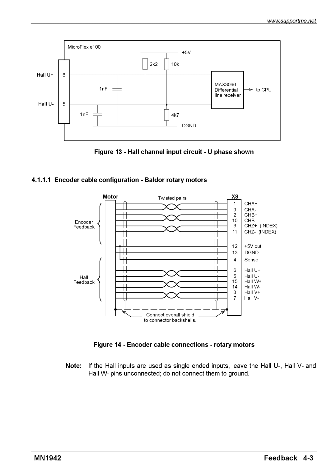
| MicroFlex e100 | +5V |
|
|
|
| |
| 2k2 | 10k |
|
Hall U+ | 6 |
|
|
| 1nF | MAX3096 | to CPU |
| Differential | ||
|
| line receiver |
|
Hall U- | 5 |
|
|
| 1nF | 4k7 |
|
|
| DGND |
|
Figure 13 - Hall channel input circuit - U phase shown
4.1.1.1 Encoder cable configuration - Baldor rotary motors
Motor | Twisted pairs | X8 |
|
|
| 1 | CHA+ |
|
| 9 | CHA- |
|
| 2 | CHB+ |
Encoder |
| 10 | CHB- |
Feedback |
| 3 | CHZ+ (INDEX) |
|
| 11 | CHZ- (INDEX) |
|
| 12 | +5V out |
|
| 13 | DGND |
|
| 4 | Sense |
|
| 6 | Hall U+ |
Hall |
| 5 | Hall U- |
Feedback |
| 15 | Hall W+ |
|
| 14 | Hall W- |
|
| 8 | Hall V+ |
|
| 7 | Hall V- |
| Connect overall shield |
|
|
| to connector backshells. |
|
|
Figure 14 - Encoder cable connections - rotary motors
Note: If the Hall inputs are used as single ended inputs, leave the Hall
MN1942 | Feedback |