www.supportme.net
3.5.1 Motor circuit contactors
If required by local codes or for safety reasons, an
![]() CAUTION: If an
CAUTION: If an
Ensure that shielding of the motor cable is continued on both sides of the contactor.
3.5.2 Motor power cable pin configuration - Baldor BSM rotary motors
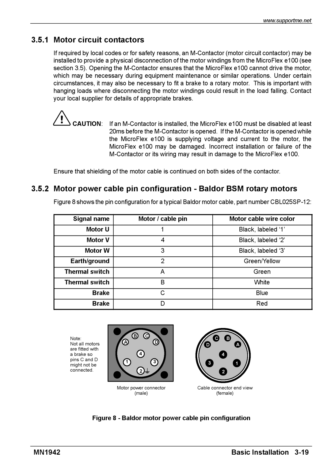
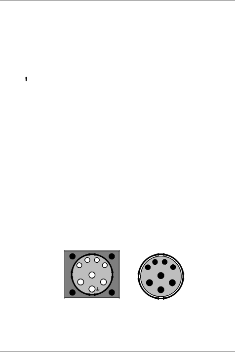
Figure 8 shows the pin configuration for a typical Baldor motor cable, part number CBL025SP-12:
Signal name | Motor / cable pin | Motor cable wire color |
|
|
|
Motor U | 1 | Black, labeled ‘1’ |
|
|
|
Motor V | 4 | Black, labeled ‘2’ |
|
|
|
Motor W | 3 | Black, labeled ‘3’ |
|
|
|
Earth/ground | 2 | Green/Yellow |
|
|
|
Thermal switch | A | Green |
|
|
|
Thermal switch | B | White |
|
|
|
Brake | C | Blue |
|
|
|
Brake | D | Red |
Note:
Not all motors are fitted with a brake so pins C and D might not be connected.
B | C |
A | D |
| 4 |
1 | 3 |
| 2 |
Motor power connector
(male)
CB
DA
4
31
2
Cable connector end view
(female)
Figure 8 - Baldor motor power cable pin configuration
MN1942 | Basic Installation |