www.supportme.net
5.4.3 Ethernet connectors
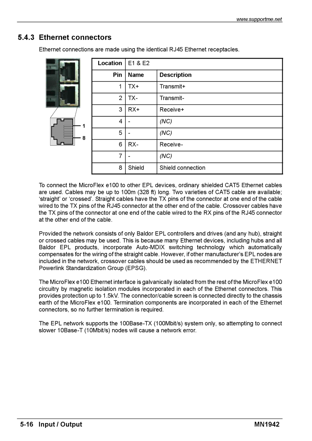
Ethernet connections are made using the identical RJ45 Ethernet receptacles.
| Location | E1 & E2 |
| |
|
|
|
| |
| Pin | Name | Description | |
|
|
|
| |
| 1 | TX+ | Transmit+ | |
|
|
|
| |
| 2 | TX- | Transmit- | |
|
|
|
| |
| 3 | RX+ | Receive+ | |
|
|
|
| |
1 | 4 | - | (NC) | |
|
|
| ||
8 | 5 | - | (NC) | |
|
|
| ||
6 | RX- | Receive- | ||
| ||||
|
|
|
| |
| 7 | - | (NC) | |
|
|
|
| |
| 8 | Shield | Shield connection | |
|
|
|
|
To connect the MicroFlex e100 to other EPL devices, ordinary shielded CAT5 Ethernet cables are used. Cables may be up to 100m (328 ft) long. Two varieties of CAT5 cable are available; ‘straight’ or ‘crossed’. Straight cables have the TX pins of the connector at one end of the cable wired to the TX pins of the RJ45 connector at the other end of the cable. Crossover cables have the TX pins of the connector at one end of the cable wired to the RX pins of the RJ45 connector at the other end of the cable.
Provided the network consists of only Baldor EPL controllers and drives (and any hub), straight or crossed cables may be used. This is because many Ethernet devices, including hubs and all Baldor EPL products, incorporate
The MicroFlex e100 Ethernet interface is galvanically isolated from the rest of the MicroFlex e100 circuitry by magnetic isolation modules incorporated in each of the Ethernet connectors. This provides protection up to 1.5kV. The connector/cable screen is connected directly to the chassis earth of the MicroFlex e100. Termination components are incorporated in each of the Ethernet connectors, so no further termination is required.
The EPL network supports the
MN1942 |