www.supportme.net
4.1.2.1SSI cable pin configuration
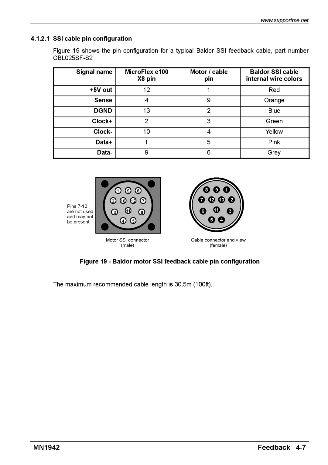
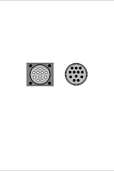
Figure 19 shows the pin configuration for a typical Baldor SSI feedback cable, part number CBL025SF-S2
Signal name | MicroFlex e100 | Motor / cable | Baldor SSI cable |
| X8 pin | pin | internal wire colors |
|
|
|
|
+5V out | 12 | 1 | Red |
|
|
|
|
Sense | 4 | 9 | Orange |
|
|
|
|
DGND | 13 | 2 | Blue |
|
|
|
|
Clock+ | 2 | 3 | Green |
|
|
|
|
Clock- | 10 | 4 | Yellow |
|
|
|
|
Data+ | 1 | 5 | Pink |
|
|
|
|
Data- | 9 | 6 | Grey |
|
|
|
|
Pins
| 1 | 9 | 8 |
2 | 10 | 12 | 7 |
3 |
| 11 | 6 |
|
| ||
| 4 | 5 |
|
Motor SSI connector
(male)
8 9 1
7 12 10 2
6 11 3
54
Cable connector end view
(female)
Figure 19 - Baldor motor SSI feedback cable pin configuration
The maximum recommended cable length is 30.5m (100ft).
MN1942 | Feedback |