www.supportme.net
5.5 CAN interface
The CAN bus is a serial based network originally developed for automotive applications, but now used for a wide range of industrial applications. It offers
The CAN protocol only defines the physical attributes of the network, i.e. the electrical, mechanical, functional and procedural parameters of the physical connection between devices. The higher level network functionality on MicroFlex e100 is defined by the CANopen protocol, one of the most used standards for machine control.
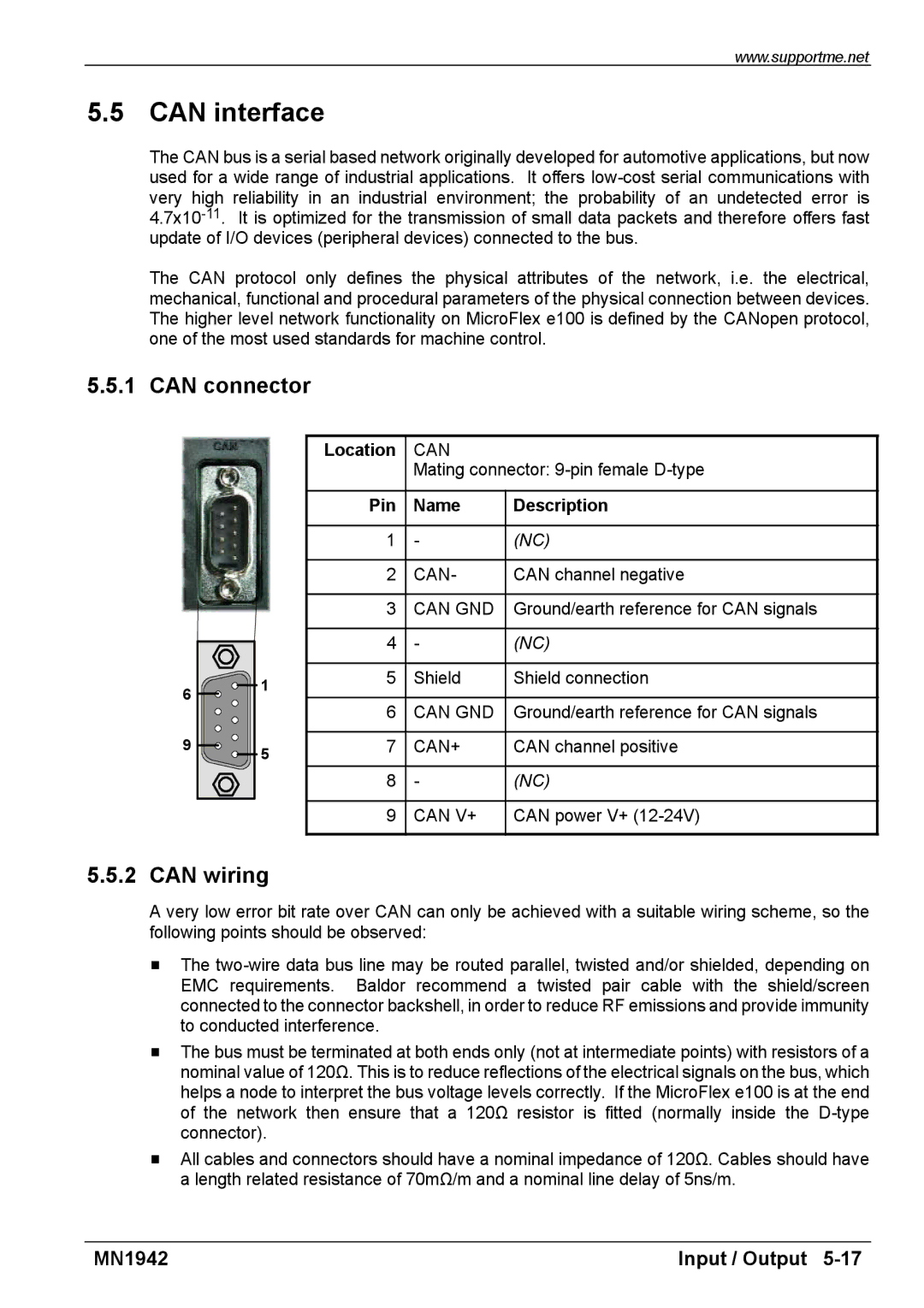
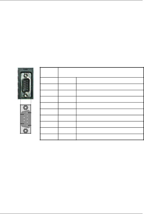
5.5.1 CAN connector
|
| Location | CAN |
|
|
|
| Mating connector: | |
|
| Pin | Name | Description |
|
| 1 | - | (NC) |
|
| 2 | CAN- | CAN channel negative |
|
| 3 | CAN GND | Ground/earth reference for CAN signals |
|
| 4 | - | (NC) |
6 | 1 | 5 | Shield | Shield connection |
|
|
| ||
| 6 | CAN GND | Ground/earth reference for CAN signals | |
|
| |||
9 | 5 | 7 | CAN+ | CAN channel positive |
|
|
|
| |
|
| 8 | - | (NC) |
|
| 9 | CAN V+ | CAN power V+ |
5.5.2 CAN wiring
A very low error bit rate over CAN can only be achieved with a suitable wiring scheme, so the following points should be observed:
HThe
HThe bus must be terminated at both ends only (not at intermediate points) with resistors of a nominal value of 120Ω. This is to reduce reflections of the electrical signals on the bus, which helps a node to interpret the bus voltage levels correctly. If the MicroFlex e100 is at the end of the network then ensure that a 120Ω resistor is fitted (normally inside the
HAll cables and connectors should have a nominal impedance of 120Ω. Cables should have a length related resistance of 70mΩ/m and a nominal line delay of 5ns/m.
MN1942 | Input / Output |