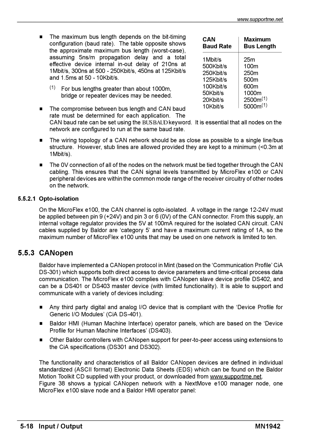
H The maximum bus length depends on the | CAN |
| Maximum | |||
| ||||||
configuration (baud rate). The table opposite shows |
| |||||
Baud Rate |
| Bus Length | ||||
the approximate maximum bus length |
| |||||
|
|
| ||||
assuming 5ns/m propagation | delay | and a total | 1Mbit/s |
| 25m | |
effective device internal | delay | of 210ns at |
| |||
500Kbit/s |
| 100m | ||||
1Mbit/s, 300ns at 500 - 250Kbit/s, 450ns at 125Kbit/s |
| |||||
250Kbit/s |
| 250m | ||||
and 1.5ms at 50 - 10Kbit/s. |
|
|
|
| ||
|
|
| 125Kbit/s |
| 500m | |
(1) For bus lengths greater than about 1000m, |
| 100Kbit/s |
| 600m | ||
bridge or repeater devices may be needed. |
| 50Kbit/s |
| 1000m | ||
| 20Kbit/s |
| 2500m(1) | |||
|
|
|
|
| ||
H The compromise between bus length and CAN baud | 10Kbit/s |
| 5000m(1) | |||
| ||||||
|
|
| ||||
rate must be determined for each application. | The |
|
|
| ||
CAN baud rate can be set using the BUSBAUD keyword. It is essential that all nodes on the network are configured to run at the same baud rate.
HThe wiring topology of a CAN network should be as close as possible to a single line/bus structure. However, stub lines are allowed provided they are kept to a minimum (<0.3m at 1Mbit/s).
HThe 0V connection of all of the nodes on the network must be tied together through the CAN cabling. This ensures that the CAN signal levels transmitted by MicroFlex e100 or CAN peripheral devices are within the common mode range of the receiver circuitry of other nodes on the network.
5.5.2.1Opto-isolation
On the MicroFlex e100, the CAN channel is
5.5.3 CANopen
Baldor have implemented a CANopen protocol in Mint (based on the ‘Communication Profile’ CiA
HAny third party digital and analog I/O device that is compliant with the ‘Device Profile for Generic I/O Modules’ (CiA
HBaldor HMI (Human Machine Interface) operator panels, which are based on the ‘Device Profile for Human Machine Interfaces’ (DS403).
HOther Baldor controllers with CANopen support for
The functionality and characteristics of all Baldor CANopen devices are defined in individual standardized (ASCII format) Electronic Data Sheets (EDS) which can be found on the Baldor Motion Toolkit CD supplied with your product, or downloaded from www.supportme.net.
Figure 38 shows a typical CANopen network with a NextMove e100 manager node, one MicroFlex e100 slave node and a Baldor HMI operator panel:
MN1942 |