www.supportme.net
4.1.2 SSI feedback
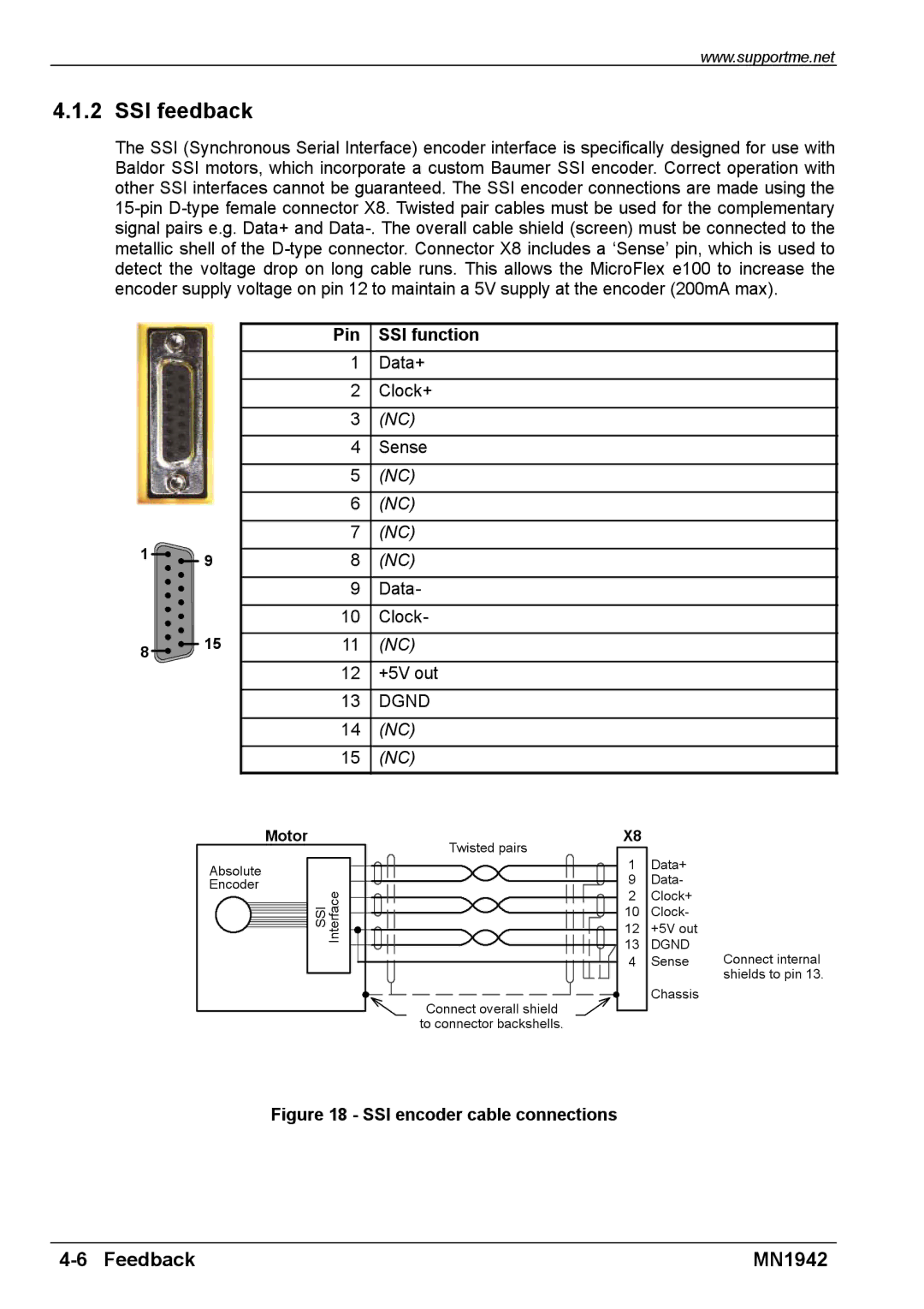
The SSI (Synchronous Serial Interface) encoder interface is specifically designed for use with Baldor SSI motors, which incorporate a custom Baumer SSI encoder. Correct operation with other SSI interfaces cannot be guaranteed. The SSI encoder connections are made using the
1 ![]()
![]() 9
9
8 ![]()
![]() 15
15
Pin SSI function
1Data+
2 Clock+
3 (NC)
4 Sense
5 (NC)
6 (NC)
7 (NC)
8 (NC)
9 Data-
10Clock-
11(NC)
12+5V out
13DGND
14(NC)
15(NC)
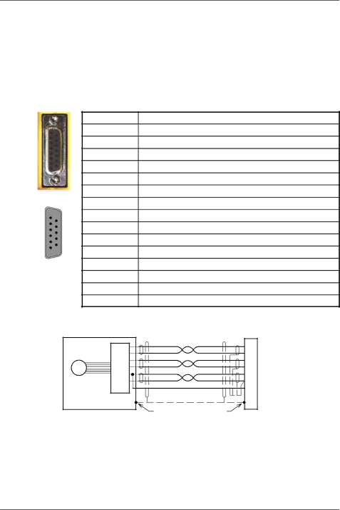
Motor |
| X8 |
|
|
|
| Twisted pairs |
|
|
Absolute |
| 1 | Data+ |
|
| 9 | Data- |
| |
Encoder |
|
| ||
SSI Interface | 2 | Clock+ |
| |
|
| |||
| 10 | Clock- |
| |
|
|
| ||
|
| 12 | +5V out |
|
|
| 13 | DGND | Connect internal |
|
| 4 | Sense | |
|
|
|
| shields to pin 13. |
|
| Connect overall shield | Chassis |
|
|
|
|
| |
|
| to connector backshells. |
|
|
Figure 18 - SSI encoder cable connections
| MN1942 |