www.supportme.net
4.1.4 EnDat (absolute encoder) feedback
The absolute encoder interface supports both incremental and absolute (multi and single turn) feedback using EnDat technology. It is possible to read and write information to the encoder. The absolute encoder connections are made using the
1 ![]()
![]() 9
9
8 ![]()
![]() 15
15
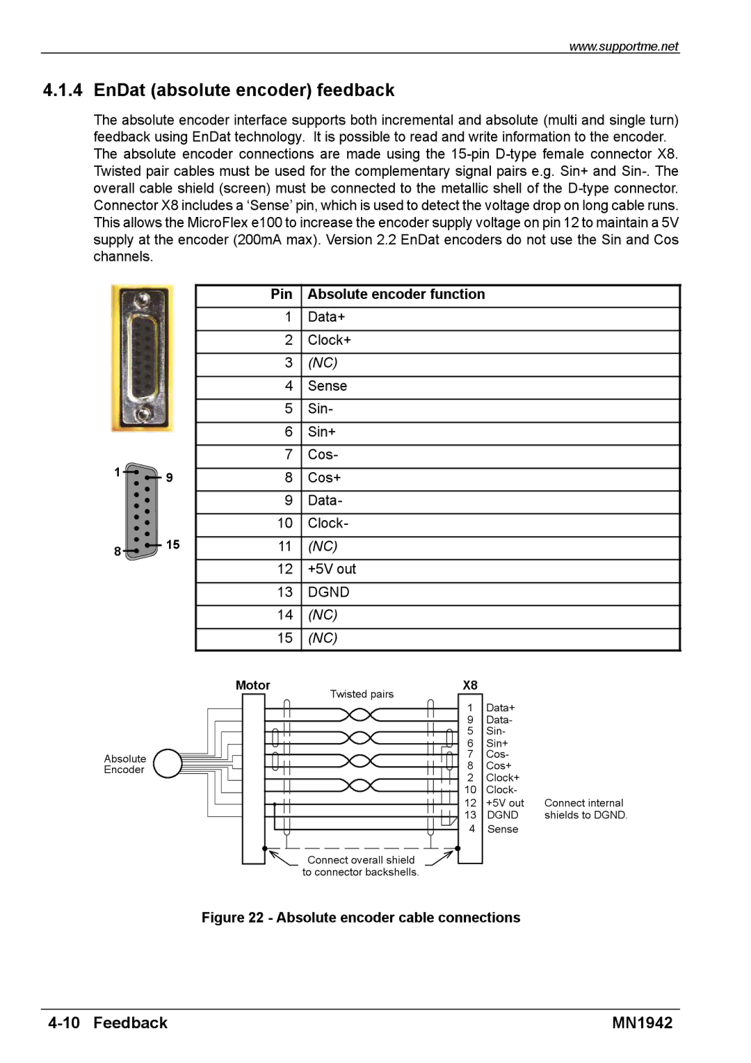
Pin Absolute encoder function
1Data+
2 Clock+
3 (NC)
4 Sense
5 Sin-
6 Sin+
7 Cos-
8 Cos+
9 Data-
10Clock-
11(NC)
12+5V out
13DGND
14(NC)
15(NC)
Absolute Encoder
Motor | Twisted pairs | X8 |
|
|
| 1 | Data+ |
| |
|
|
| ||
|
| 9 | Data- |
|
|
| 5 | Sin- |
|
|
| 6 | Sin+ |
|
|
| 7 | Cos- |
|
|
| 8 | Cos+ |
|
|
| 2 | Clock+ |
|
|
| 10 | Clock- |
|
|
| 12 | +5V out | Connect internal |
|
| 13 | DGND | shields to DGND. |
|
| 4 | Sense |
|
| Connect overall shield |
|
|
|
| to connector backshells. |
|
|
|
Figure 22 - Absolute encoder cable connections
| MN1942 |